


Duplication prohibited
MIR 9000
Environnement
S.A
5–25
JULY 2009
5.3.5
ADJUSTMENT OF THE AMPLIFICATION CHAIN
5.3.5.1 Fixed
amplification
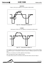
Connect the probe of channel 1 of the oscilloscope to test point Pt 23. Make sure that the signal is
symmetrical with regard to the base line (GND). When necessary, activate P10 to adjust the signal.
Connect the probe of channel 2 of the oscilloscope to test point Pt 0. Check that the width of the signal
is identical. Amplification on the signal of channel 1 (point Pt23) should be nil (potentiometer P11).
Connect the probe of channel 1 of the oscilloscope to test point Pt 11.
In the “Configuration / Software /Analyzer configuration” menu, adjust the
Static Gain
variable to 200
(fixed gain at 200). Start a "ZERO-REF" cycle.
Once the "ZERO-REF" cycle has ended, put the analyzer in "ZERO" mode (in “ZERO ANALYZER”
mode with the TIG option).
The signal in Pt11 should be symmetrical with regard to the base line (GND). Adjustment is made
using P2.
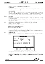
Identify the most important signal using an oscilloscope. Visualize the value in points in the ”Tests /
Optical Bench”
menu. The position measurement corresponds to the S signal and the reference
position corresponds to the SR signal.
The maximum value of the signal is 65535 pts (saturation AD 16 bits).
5.3.5.2
Searching for the saturation line
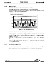
Make sure that the oscilloscope is in "DC". Using P3, search for the saturation line of the signal in
Pt11. Saturation should be close to 13.6 to 14 volts.
Display this on the screen in order to have a visual reference for continuing with the adjustments.
Using P3, adjust the most important signal 2 volts below the saturation line, namely at 12 volts.
5.3.5.3 Automatic
amplification
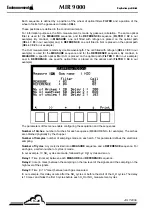
In the “Tests / Optical Bench” menu, read the value in points of the most important signal. The
Auto
Gain
variable corresponds to this value, rounded up top the lower value by 10 000 points (for
example, if the most important signal is at 56800 points, it will take the value as 50 000 pts).
In the “Configuration / Software /Analyzer configuration” menu, adjust the
Static Gain
variable to 00
(validates the automatic gain). To work in automatic mode with the same width on each signal,
program the
Auto Gain
variable to the value shown above (
Auto Gain
: 50,000 in our example). Start a
Zero Ref.
Check the signals in Pt11 and Pt17.
If the signal appears saturated in Pt17, take up the fixed amplification again by reducing the most
important signal by 2 volts (signal at 10 volts).
Summary of Contents for Envea MIR 9000
Page 10: ...Duplication prohibited MIR 9000 EnvironnementS A 0 10 JULY 2009 Page intentionally left blank...
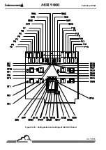
Page 22: ...EnvironnementS A MIR 9000 Duplication prohibited 1 12 JULY 2009 Figure 1 7 Analysis cabinet...
Page 27: ...Duplication prohibited MIR 9000 EnvironnementS A 1 17 JULY 2009 Page intentionally left blank...
Page 35: ...Duplication prohibited MIR 9000 EnvironnementS A 2 5 JULY 2009 Page intentionally left blank...
Page 102: ...EnvironnementS A MIR 9000 Duplication prohibited 4 2 JULY 2009 Page intentionality left blank...
Page 157: ......
Page 159: ......
Page 161: ......
Page 163: ...EnvironnementS A MIR 9000 Duplication prohibited 6 10 JULY 2009 Figure 6 4 Oxygen probe...
Page 165: ...EnvironnementS A MIR 9000 Duplication prohibited 6 12 JULY 2009 Page intentionally left blank...
Page 180: ...EnvironnementS A MIR 9000 Duplication prohibited 6 22 JULY 2009 Page intentionally left blank...
Page 182: ...EnvironnementS A MIR 9000 Duplication prohibited 7 2 JULY 2009 Page left intentionally blank...
Page 206: ...EnvironnementS A MIR 9000 Duplication prohibited 7 28 JULY 2009 Page left intentionally blank...
Page 212: ...EnvironnementS A DAC8 board Duplication prohibited MARCH 2018 6 Page intentionally left blank...