


254
WSG-1068 ENGINE CONTROLS
speeds (with customer-specified minimum and
maximum) based on a variable signal input.
It can be an electronic replacement for a throttle
cable with maximum speed governing (throttle-
bywire).
Or it can switch between throttle-by-wire and a
second fixed or variable input based on a
neutral/parking brake signal.
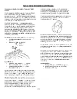
With the GCP system, a laptop and a communications
cable, diagnosis becomes simpler. The technician can
either view engine data with a real time graphing
program, or store that data into a numeric data file.
Every time a fault is set, the laptop will give you detailed
information about the fault, including:
when it happened
if the fault still exists
a list of essential engine data from the time of
the fault.
It can also display a 10 second graph of critical engine
data, from 8 seconds before the fault occurred to two
seconds after. And if you only want to view engine
parameters and fault codes, all you need is a Personal
Digital Assistant (PDA) and our easy to load software
and a communications cable.
With many OEMs using control modules to control their
machinery, the GCP has the ability to communicate
engine data to and receive commands from other
control modules through a Controller Area Network
(CAN) link, with messages written in the J1939 protocol.
This allows large amounts of data to move throughout
the machine through only two wires, and can be used to
run some module based gauge packages.
The GCP also carries auxiliary features that can be
programmed to control OEM devices, allowing the OEM
to eliminate components from their machinery.
The GCP is also equipped with multiple safety and
protection devices that protect the user and engine from
hazards such as:
over
speed
over
temperature
over
voltage
low oil pressure
unauthorized
tampering
over cranking starter motor.
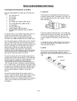
The GCP controls the following:
Fuel metering system
Ignition
timing
On-board diagnostics for engine functions
The GCP constantly observes the information from
various sensors. The GCP controls the systems that
affect engine performance. The GCP performs the
diagnostic function of the system. It can recognize
operational problems, alert the operator through the
Malfunction Indicator Lamp (MIL), and store diagnostic
trouble codes (DTC’s). DTC’s identify the problem
areas to aid the technician in making repairs.
The GCP supplies either 5 or 12 volts to power various
sensors or switches. The power is supplied through
resistances in the GCP which are so high in value that
a test light will not light when connected to the circuit. In
some cases, even an ordinary shop voltmeter will not
give an accurate reading because its resistance is too
low. Therefore, a digital voltmeter with at least 10
megohms input impedance is required to ensure
accurate voltage readings. The GCP controls output
circuits such as the fuel injectors, electronic governor,
etc., by controlling the ground or the power feed circuit
through transistors or other solid state devices.
The GCP is designed to maintain exhaust emission
levels to government mandated standards while
providing excellent operation and fuel efficiency. The
GCP monitors numerous engine functions via electronic
sensors such as the throttle position (TP) sensor and
the heated oxygen sensor (HO2S).
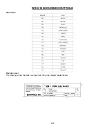
GCP Inputs (operating conditions read)
Engine Coolant Temperature
Crankshaft
Position
Exhaust Oxygen Content
Manifold Absolute Pressure
Battery
Voltage
Throttle Position / Electronic Actuator
Fuel Pump Voltage
Intake Air Temperature
Camshaft
Position
GCP Outputs (systems controlled)
Fuel
control
Electronic Throttle Control
Electric
Fuel
Pump
Diagnostics - Malfunction Indicator Lamp (check
engine
lamp)
Diagnostics - Data Link Connector (DLC)
Summary of Contents for WSG-1068
Page 1: ...WSG 1068 6 8 LITER INDUSTRIAL ENGINE SERVICE MANUAL EDI 1050180 March 2009 ...
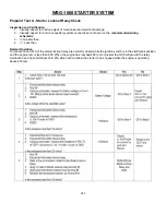
Page 12: ...6 WSG 1068 GENERAL INFORMATION DIAGNOSIS AND TESTING Special Tools ...
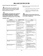
Page 14: ...8 WSG 1068 GENERAL INFORMATION Symptom Chart Condition Possible Source Action ...
Page 15: ...9 WSG 1068 GENERAL INFORMATION ...
Page 48: ...32 WSG 1068 ENGINE Module View ...
Page 49: ...33 WSG 1068 ENGINE Engine Intake Components ...
Page 50: ...34 WSG 1068 ENGINE ...
Page 51: ...35 WSG 1068 ENGINE Low End Components ...
Page 52: ...36 WSG 1068 ENGINE ...
Page 53: ...37 WSG 1068 ENGINE Upper End Components ...
Page 54: ...38 WSG 1068 ENGINE ...
Page 55: ...39 WSG 1068 ENGINE Major Front End Components ...
Page 56: ...40 WSG 1068 ENGINE DIAGNOSIS AND TESTING Refer to Section 01 for basic mechanical concerns ...
Page 65: ...49 WSG 1068 ENGINE 4 Tighten the nuts and bolts in the sequence shown ...
Page 68: ...52 WSG 1068 ENGINE 4 Tighten the bolts in the sequence shown 5 Reinstall the PCV valve ...
Page 75: ...59 WSG 1068 ENGINE ...
Page 87: ...71 WSG 1068 ENGINE Camshaft Assembly Timing Mark Alignment ...
Page 88: ...72 WSG 1068 ENGINE Timing Chains Camshaft Gears and Crankshaft Gears Alignment ...
Page 137: ...121 WSG 1068 ENGINE 1 Remove the Camshaft Holding Tool from the camshaft 6250 ...
Page 143: ...127 WSG 1068 ENGINE 10 Install the roller followers 11 Remove the Valve Spring Spacer ...
Page 155: ...139 WSG 1068 ENGINE 35 Install the timing chain guides 6K297 ...
Page 172: ...156 WSG 1068 ENGINE SPECIFICATIONS ...
Page 173: ...157 WSG 1068 ENGINE ...
Page 174: ...158 WSG 1068 ENGINE ...
Page 180: ...164 WSG 1068 IGNITION SYSTEM ...
Page 188: ...172 WSG 1068 IGNITION SYSTEM Firing Order ...
Page 190: ...174 WSG 1068 IGNITION SYSTEM Harness Connector Pinout Description I O Input Output ...
Page 194: ...178 WSG 1068 IGNITION SYSTEM Engine Controls ...
Page 195: ...179 WSG 1068 IGNITION SYSTEM Engine Sensors part of SK2U1L 12A200 BA ...
Page 197: ...181 WSG 1068 IGNITION SYSTEM 90 Pin GCP Connector ...
Page 199: ...183 WSG 1068 IGNITION SYSTEM ...
Page 204: ...188 WSG 1068 FUEL SYSTEM ...
Page 225: ...209 WSG 1068 COOLING SYSTEM CHT Sensor Data Temperature Sensor Characteristics ...
Page 229: ...213 WSG 1068 COOLING SYSTEM PINPOINT TEST A LOSS OF COOLANT ...
Page 230: ...214 WSG 1068 COOLING SYSTEM PINPOINT TEST A LOSS OF COOLANT Continued ...
Page 232: ...216 WSG 1068 COOLING SYSTEM PINPOINT TEST B THE ENGINE OVERHEATS Continued ...
Page 233: ...217 WSG 1068 COOLING SYSTEM ...
Page 234: ...218 PINPOINT TEST B THE ENGINE OVERHEATS Continued WSG 1068 COOLING SYSTEM ...
Page 239: ...223 WSG 1068 CHARGING SYSTEM DIAGNOSIS AND TESTING Recommended Accessory Wiring ...
Page 243: ...227 WSG 1068 CHARGING SYSTEM Symptom Chart ...
Page 245: ...229 WSG 1068 CHARGING SYSTEM ...
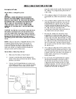
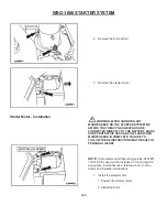
Page 259: ...243 WSG 1068 STARTER SYSTEM ...
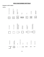
Page 278: ...262 WSG 1068 ENGINE CONTROLS Diagrams and Schematics Symbols ...
Page 279: ...263 WSG 1068 ENGINE CONTROLS GCP Power Distribution Box ...
Page 281: ...265 WSG 1068 ENGINE CONTROLS Power Distribution ...
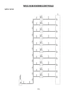
Page 282: ...266 WSG 1068 ENGINE CONTROLS Ignition System ...
Page 283: ...267 WSG 1068 ENGINE CONTROLS Starting System ...
Page 284: ...268 WSG 1068 ENGINE CONTROLS Charging System ...
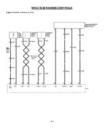
Page 285: ...269 WSG 1068 ENGINE CONTROLS Engine Controls Sensors 1 of 2 ...
Page 286: ...270 WSG 1068 ENGINE CONTROLS Engine Controls Sensors 2 of 2 ...
Page 287: ...271 WSG 1068 ENGINE CONTROLS Fuel Injectors ...
Page 289: ...273 Engine Controls Dry Fuel EPR ...
Page 290: ...274 WSG 1068 ENGINE CONTROLS Engine Component Locator View ...
Page 305: ...289 WSG 1068 ENGINE CONTROLS Engine Performance While Under Load ...
Page 306: ...290 WSG 1068 ENGINE CONTROLS Engine Concerns ...
Page 315: ...299 WSG 1068 ENGINE CONTROLS SPECIFICATIONS ...
Page 320: ...304 WSG 1068 METRICS ENGLISH METRIC CONVERSION ...
Page 321: ...305 WSG 1068 METRICS DECIMAL AND METRIC EQUIVALENTS TORQUE CONVERSION ...
Page 323: ...307 WSG 1068 METRICS ...
Page 324: ...308 WSG 1068 METRICS ...
Page 325: ...309 WSG 1068 METRICS ...
Page 326: ...310 WSG 1068 METRICS ...
Page 327: ...311 WSG 1068 METRICS ...
Page 328: ...312 WSG 1068 METRICS ...
Page 329: ...313 WSG 1068 METRICS ...
Page 330: ...314 ...