


4
WSG-1068 GENERAL INFORMATION
Excessive Engine Oil Consumption
The amount of oil an engine uses will vary with the way
the equipment is driven in addition to normal engine-to
engine variation. This is especially true during the first
340 hours or 16,100 km (10,000 miles) when a new
engine is being broken in or until certain internal engine
components become conditioned. Engines used in
heavy-duty operation may use more oil. The following
are examples of heavy-duty operation:
severe loading applications
sustained high speed operation
Engines need oil to lubricate the following internal
components:
cylinder block, cylinder walls
pistons, piston pins and rings
intake and exhaust valve stems
intake and exhaust valve guides
all internal engine components
When the pistons move downward, a thin film of oil is
left on the cylinder walls. As the engine is operated,
some oil is also drawn into the combustion chambers
past the intake and exhaust valve stem seals and
burned.
The following is a partial list of conditions that can affect
oil consumption rates:
engine
size
operator driving habits
ambient
temperature
quality and viscosity of the oil
Operating under varying conditions can frequently be
misleading. An engine that has been run for short hours
or in below-freezing ambient temperatures may have
consumed a “normal” amount of oil. However, when
checking engine oil level, it may measure up to the full
mark on the oil level dipstick due to dilution
(condensation and fuel) in the engine crankcase. The
engine might then be run at high speeds where the
condensation and fuel boil off. The next time the engine
oil is checked, it may appear that a liter (quart) of oil was
used in about 3 to 3-1/2 hours. This perceived 3 to 3-1/
2 hours per liter (quart) oil consumption rate causes
customer concern even though the actual overall oil
consumption rate is about 50 hours per liter (quart).
Make sure the selected engine oil meets Ford
specification WSS-M2C153-F and the recommended
API performance category “SJ” or higher and SAE
viscosity grade as shown in the equipment Owner’s or
Operators Engine handbook. It is also important that the
engine oil is changed at the intervals specified. Refer to
the Engine Operator’s handbook.
Oil Consumption Test
The following diagnostic procedure is used to determine
the source of excessive internal oil consumption.
NOTE:
Oil use is normally greater during the first 300
hours of service. As hours increase, oil use generally
decreases. Engines in normal service should get at
least 31.7 hours per quart (900 miles per quart) after
300 hours of service. High speeds, heavy loads, high
ambient temperature and other factors may result in
greater oil use.
1. Determine customer’s engine load habits, such
as sustained high speed operation, extended
idle, heavy work loads and other considerations.
2. Verify that the engine has no external oil leak as
described under Engine Oil Leaks in the
Diagnosis and Testing portion of this section.
3. Verify that the engine has the correct oil level
dipstick.
4. Verify that the engine is not being run in an
overfilled condition. Check the oil level at least
five minutes after a hot shutdown with the
engine/vehicle parked on a level surface. In no
case should the level be above the top of the
cross-hatched area and the letter F in FULL. If
significantly overfilled, perform steps 5 through
9. If not proceed to step 10.
5. Drain the engine oil, remove and replace the oil
bypass filter and refill with one quart less than
the recommended amount.
6. Run the engine for three minutes (10 minutes if
cold), and allow the oil to drain back for at least
five minutes with the engine/vehicle on a level
surface.
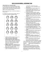
7. Remove oil level dipstick and wipe clean.
CAUTION: Do not wipe with anything contaminated
with silicone compounds.
8. Reinstall the oil level dipstick, being sure to seat
it firmly in the oil level indicator tube. Remove
the oil level dipstick and draw a mark on the
back (unmarked) surface at the indicated oil
level. This level should be about the same as
the ADD mark on the face of the oil level
dipstick.
9. Add one quart of oil. Restart the engine and
allow to idle for at least two minutes. Shut off
the engine and allow the oil to drain back for at
least five minutes. Mark the oil level dipstick,
using the procedure above. This level may
range from slightly below the top of the cross-
hatched area to slightly below the letter F in
FULL.
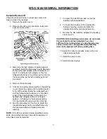
10. Record the vehicle mileage or hours.
Summary of Contents for WSG-1068
Page 1: ...WSG 1068 6 8 LITER INDUSTRIAL ENGINE SERVICE MANUAL EDI 1050180 March 2009 ...
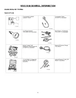
Page 12: ...6 WSG 1068 GENERAL INFORMATION DIAGNOSIS AND TESTING Special Tools ...
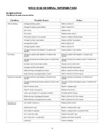
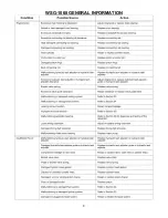
Page 14: ...8 WSG 1068 GENERAL INFORMATION Symptom Chart Condition Possible Source Action ...
Page 15: ...9 WSG 1068 GENERAL INFORMATION ...
Page 48: ...32 WSG 1068 ENGINE Module View ...
Page 49: ...33 WSG 1068 ENGINE Engine Intake Components ...
Page 50: ...34 WSG 1068 ENGINE ...
Page 51: ...35 WSG 1068 ENGINE Low End Components ...
Page 52: ...36 WSG 1068 ENGINE ...
Page 53: ...37 WSG 1068 ENGINE Upper End Components ...
Page 54: ...38 WSG 1068 ENGINE ...
Page 55: ...39 WSG 1068 ENGINE Major Front End Components ...
Page 56: ...40 WSG 1068 ENGINE DIAGNOSIS AND TESTING Refer to Section 01 for basic mechanical concerns ...
Page 65: ...49 WSG 1068 ENGINE 4 Tighten the nuts and bolts in the sequence shown ...
Page 68: ...52 WSG 1068 ENGINE 4 Tighten the bolts in the sequence shown 5 Reinstall the PCV valve ...
Page 75: ...59 WSG 1068 ENGINE ...
Page 87: ...71 WSG 1068 ENGINE Camshaft Assembly Timing Mark Alignment ...
Page 88: ...72 WSG 1068 ENGINE Timing Chains Camshaft Gears and Crankshaft Gears Alignment ...
Page 137: ...121 WSG 1068 ENGINE 1 Remove the Camshaft Holding Tool from the camshaft 6250 ...
Page 143: ...127 WSG 1068 ENGINE 10 Install the roller followers 11 Remove the Valve Spring Spacer ...
Page 155: ...139 WSG 1068 ENGINE 35 Install the timing chain guides 6K297 ...
Page 172: ...156 WSG 1068 ENGINE SPECIFICATIONS ...
Page 173: ...157 WSG 1068 ENGINE ...
Page 174: ...158 WSG 1068 ENGINE ...
Page 180: ...164 WSG 1068 IGNITION SYSTEM ...
Page 188: ...172 WSG 1068 IGNITION SYSTEM Firing Order ...
Page 190: ...174 WSG 1068 IGNITION SYSTEM Harness Connector Pinout Description I O Input Output ...
Page 194: ...178 WSG 1068 IGNITION SYSTEM Engine Controls ...
Page 195: ...179 WSG 1068 IGNITION SYSTEM Engine Sensors part of SK2U1L 12A200 BA ...
Page 197: ...181 WSG 1068 IGNITION SYSTEM 90 Pin GCP Connector ...
Page 199: ...183 WSG 1068 IGNITION SYSTEM ...
Page 204: ...188 WSG 1068 FUEL SYSTEM ...
Page 225: ...209 WSG 1068 COOLING SYSTEM CHT Sensor Data Temperature Sensor Characteristics ...
Page 229: ...213 WSG 1068 COOLING SYSTEM PINPOINT TEST A LOSS OF COOLANT ...
Page 230: ...214 WSG 1068 COOLING SYSTEM PINPOINT TEST A LOSS OF COOLANT Continued ...
Page 232: ...216 WSG 1068 COOLING SYSTEM PINPOINT TEST B THE ENGINE OVERHEATS Continued ...
Page 233: ...217 WSG 1068 COOLING SYSTEM ...
Page 234: ...218 PINPOINT TEST B THE ENGINE OVERHEATS Continued WSG 1068 COOLING SYSTEM ...
Page 239: ...223 WSG 1068 CHARGING SYSTEM DIAGNOSIS AND TESTING Recommended Accessory Wiring ...
Page 243: ...227 WSG 1068 CHARGING SYSTEM Symptom Chart ...
Page 245: ...229 WSG 1068 CHARGING SYSTEM ...
Page 259: ...243 WSG 1068 STARTER SYSTEM ...
Page 278: ...262 WSG 1068 ENGINE CONTROLS Diagrams and Schematics Symbols ...
Page 279: ...263 WSG 1068 ENGINE CONTROLS GCP Power Distribution Box ...
Page 281: ...265 WSG 1068 ENGINE CONTROLS Power Distribution ...
Page 282: ...266 WSG 1068 ENGINE CONTROLS Ignition System ...
Page 283: ...267 WSG 1068 ENGINE CONTROLS Starting System ...
Page 284: ...268 WSG 1068 ENGINE CONTROLS Charging System ...
Page 285: ...269 WSG 1068 ENGINE CONTROLS Engine Controls Sensors 1 of 2 ...
Page 286: ...270 WSG 1068 ENGINE CONTROLS Engine Controls Sensors 2 of 2 ...
Page 287: ...271 WSG 1068 ENGINE CONTROLS Fuel Injectors ...
Page 289: ...273 Engine Controls Dry Fuel EPR ...
Page 290: ...274 WSG 1068 ENGINE CONTROLS Engine Component Locator View ...
Page 305: ...289 WSG 1068 ENGINE CONTROLS Engine Performance While Under Load ...
Page 306: ...290 WSG 1068 ENGINE CONTROLS Engine Concerns ...
Page 315: ...299 WSG 1068 ENGINE CONTROLS SPECIFICATIONS ...
Page 320: ...304 WSG 1068 METRICS ENGLISH METRIC CONVERSION ...
Page 321: ...305 WSG 1068 METRICS DECIMAL AND METRIC EQUIVALENTS TORQUE CONVERSION ...
Page 323: ...307 WSG 1068 METRICS ...
Page 324: ...308 WSG 1068 METRICS ...
Page 325: ...309 WSG 1068 METRICS ...
Page 326: ...310 WSG 1068 METRICS ...
Page 327: ...311 WSG 1068 METRICS ...
Page 328: ...312 WSG 1068 METRICS ...
Page 329: ...313 WSG 1068 METRICS ...
Page 330: ...314 ...