


166
WSG-1068 IGNITION SYSTEM
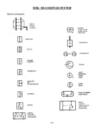
Overview
The Ignition System is designed to ignite the
compressed air/fuel mixture in an internal combustion
engine by a high voltage spark from an ignition coil. The
ignition system also provides engine timing information
to the GCP for proper engine operation and misfire
detection.
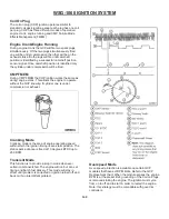
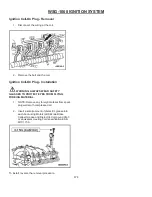
Electronic Ignition System
The Coil On Plug (COP) EI System uses a separate coil
per spark plug and each coil is mounted directly onto the
plug. The COP EI System eliminates the need for spark
plug wires but does require input from the camshaft
position (CMP) sensor. Operation of the components are
as follows:
1.
Note:
Electronic Ignition engine timing is entirely
controlled by the GCP. Electronic Ignition engine
timing is NOT adjustable. Do not attempt to
check base timing. You will receive false
readings.
2. The GCP uses the CMP sensor not shown on
COP EI Systems to identify top dead center of
compression of cylinder 1 to synchronize the
firing of the individual coils.
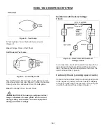
3. The GCP acts as an electronic switch to ground
in the coil primary circuit. When the switch is
closed, battery positive voltage (B+) applied to
the coil primary circuit builds a magnetic field
around the primary coil. When the switch opens,
the power is interrupted and the primary field
collapses inducing the high voltage in the
secondary coil windings and the spark plug is
fired. A kickback voltage spike occurs when the
primary field collapses.
4. The GCP processes the CKP signal and uses it
to drive the tachometer as the Clean Tach Out
(CTO) signal.
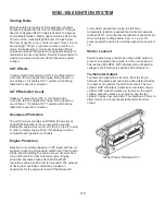
Starting RPM
The program strategy requires the engine to obtain a
minimum of 100-140 RPM before the GCP will allow
ignition spark to be generated. Any failure with an
auxiliary system can cause excessive engine crank
(load) force, which may cause the engine too not reach
the required starting RPM. Perform a thorough
inspection of all auxiliary systems and components,
inspect for binding hydraulic pumps and misalignment of
drive systems.
Camshaft Position Sensor
The Camshaft Position (CMP) Sensor detects the
position of the camshaft. The CMP Sensor identifies
when piston #1 is on its compression stroke.
The CMP Sensor is a magnetic transducer mounted on
the engine front cover adjacent to the camshaft. By
monitoring a target on the camshaft sprocket, the CMP
sensor identifies cylinder one to the GCP. The COP EI
system uses this information to synchronize the firing of
the individual coils.
Summary of Contents for WSG-1068
Page 1: ...WSG 1068 6 8 LITER INDUSTRIAL ENGINE SERVICE MANUAL EDI 1050180 March 2009 ...
Page 12: ...6 WSG 1068 GENERAL INFORMATION DIAGNOSIS AND TESTING Special Tools ...
Page 14: ...8 WSG 1068 GENERAL INFORMATION Symptom Chart Condition Possible Source Action ...
Page 15: ...9 WSG 1068 GENERAL INFORMATION ...
Page 48: ...32 WSG 1068 ENGINE Module View ...
Page 49: ...33 WSG 1068 ENGINE Engine Intake Components ...
Page 50: ...34 WSG 1068 ENGINE ...
Page 51: ...35 WSG 1068 ENGINE Low End Components ...
Page 52: ...36 WSG 1068 ENGINE ...
Page 53: ...37 WSG 1068 ENGINE Upper End Components ...
Page 54: ...38 WSG 1068 ENGINE ...
Page 55: ...39 WSG 1068 ENGINE Major Front End Components ...
Page 56: ...40 WSG 1068 ENGINE DIAGNOSIS AND TESTING Refer to Section 01 for basic mechanical concerns ...
Page 65: ...49 WSG 1068 ENGINE 4 Tighten the nuts and bolts in the sequence shown ...
Page 68: ...52 WSG 1068 ENGINE 4 Tighten the bolts in the sequence shown 5 Reinstall the PCV valve ...
Page 75: ...59 WSG 1068 ENGINE ...
Page 87: ...71 WSG 1068 ENGINE Camshaft Assembly Timing Mark Alignment ...
Page 88: ...72 WSG 1068 ENGINE Timing Chains Camshaft Gears and Crankshaft Gears Alignment ...
Page 137: ...121 WSG 1068 ENGINE 1 Remove the Camshaft Holding Tool from the camshaft 6250 ...
Page 143: ...127 WSG 1068 ENGINE 10 Install the roller followers 11 Remove the Valve Spring Spacer ...
Page 155: ...139 WSG 1068 ENGINE 35 Install the timing chain guides 6K297 ...
Page 172: ...156 WSG 1068 ENGINE SPECIFICATIONS ...
Page 173: ...157 WSG 1068 ENGINE ...
Page 174: ...158 WSG 1068 ENGINE ...
Page 180: ...164 WSG 1068 IGNITION SYSTEM ...
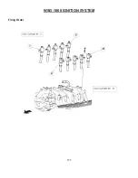
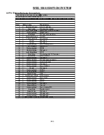
Page 188: ...172 WSG 1068 IGNITION SYSTEM Firing Order ...
Page 190: ...174 WSG 1068 IGNITION SYSTEM Harness Connector Pinout Description I O Input Output ...
Page 194: ...178 WSG 1068 IGNITION SYSTEM Engine Controls ...
Page 195: ...179 WSG 1068 IGNITION SYSTEM Engine Sensors part of SK2U1L 12A200 BA ...
Page 197: ...181 WSG 1068 IGNITION SYSTEM 90 Pin GCP Connector ...
Page 199: ...183 WSG 1068 IGNITION SYSTEM ...
Page 204: ...188 WSG 1068 FUEL SYSTEM ...
Page 225: ...209 WSG 1068 COOLING SYSTEM CHT Sensor Data Temperature Sensor Characteristics ...
Page 229: ...213 WSG 1068 COOLING SYSTEM PINPOINT TEST A LOSS OF COOLANT ...
Page 230: ...214 WSG 1068 COOLING SYSTEM PINPOINT TEST A LOSS OF COOLANT Continued ...
Page 232: ...216 WSG 1068 COOLING SYSTEM PINPOINT TEST B THE ENGINE OVERHEATS Continued ...
Page 233: ...217 WSG 1068 COOLING SYSTEM ...
Page 234: ...218 PINPOINT TEST B THE ENGINE OVERHEATS Continued WSG 1068 COOLING SYSTEM ...
Page 239: ...223 WSG 1068 CHARGING SYSTEM DIAGNOSIS AND TESTING Recommended Accessory Wiring ...
Page 243: ...227 WSG 1068 CHARGING SYSTEM Symptom Chart ...
Page 245: ...229 WSG 1068 CHARGING SYSTEM ...
Page 259: ...243 WSG 1068 STARTER SYSTEM ...
Page 278: ...262 WSG 1068 ENGINE CONTROLS Diagrams and Schematics Symbols ...
Page 279: ...263 WSG 1068 ENGINE CONTROLS GCP Power Distribution Box ...
Page 281: ...265 WSG 1068 ENGINE CONTROLS Power Distribution ...
Page 282: ...266 WSG 1068 ENGINE CONTROLS Ignition System ...
Page 283: ...267 WSG 1068 ENGINE CONTROLS Starting System ...
Page 284: ...268 WSG 1068 ENGINE CONTROLS Charging System ...
Page 285: ...269 WSG 1068 ENGINE CONTROLS Engine Controls Sensors 1 of 2 ...
Page 286: ...270 WSG 1068 ENGINE CONTROLS Engine Controls Sensors 2 of 2 ...
Page 287: ...271 WSG 1068 ENGINE CONTROLS Fuel Injectors ...
Page 289: ...273 Engine Controls Dry Fuel EPR ...
Page 290: ...274 WSG 1068 ENGINE CONTROLS Engine Component Locator View ...
Page 305: ...289 WSG 1068 ENGINE CONTROLS Engine Performance While Under Load ...
Page 306: ...290 WSG 1068 ENGINE CONTROLS Engine Concerns ...
Page 315: ...299 WSG 1068 ENGINE CONTROLS SPECIFICATIONS ...
Page 320: ...304 WSG 1068 METRICS ENGLISH METRIC CONVERSION ...
Page 321: ...305 WSG 1068 METRICS DECIMAL AND METRIC EQUIVALENTS TORQUE CONVERSION ...
Page 323: ...307 WSG 1068 METRICS ...
Page 324: ...308 WSG 1068 METRICS ...
Page 325: ...309 WSG 1068 METRICS ...
Page 326: ...310 WSG 1068 METRICS ...
Page 327: ...311 WSG 1068 METRICS ...
Page 328: ...312 WSG 1068 METRICS ...
Page 329: ...313 WSG 1068 METRICS ...
Page 330: ...314 ...