


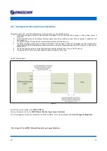

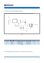


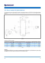


5.9 How to connect an LCD display
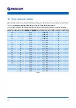
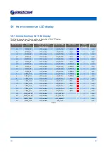
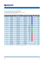
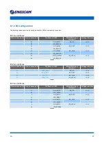
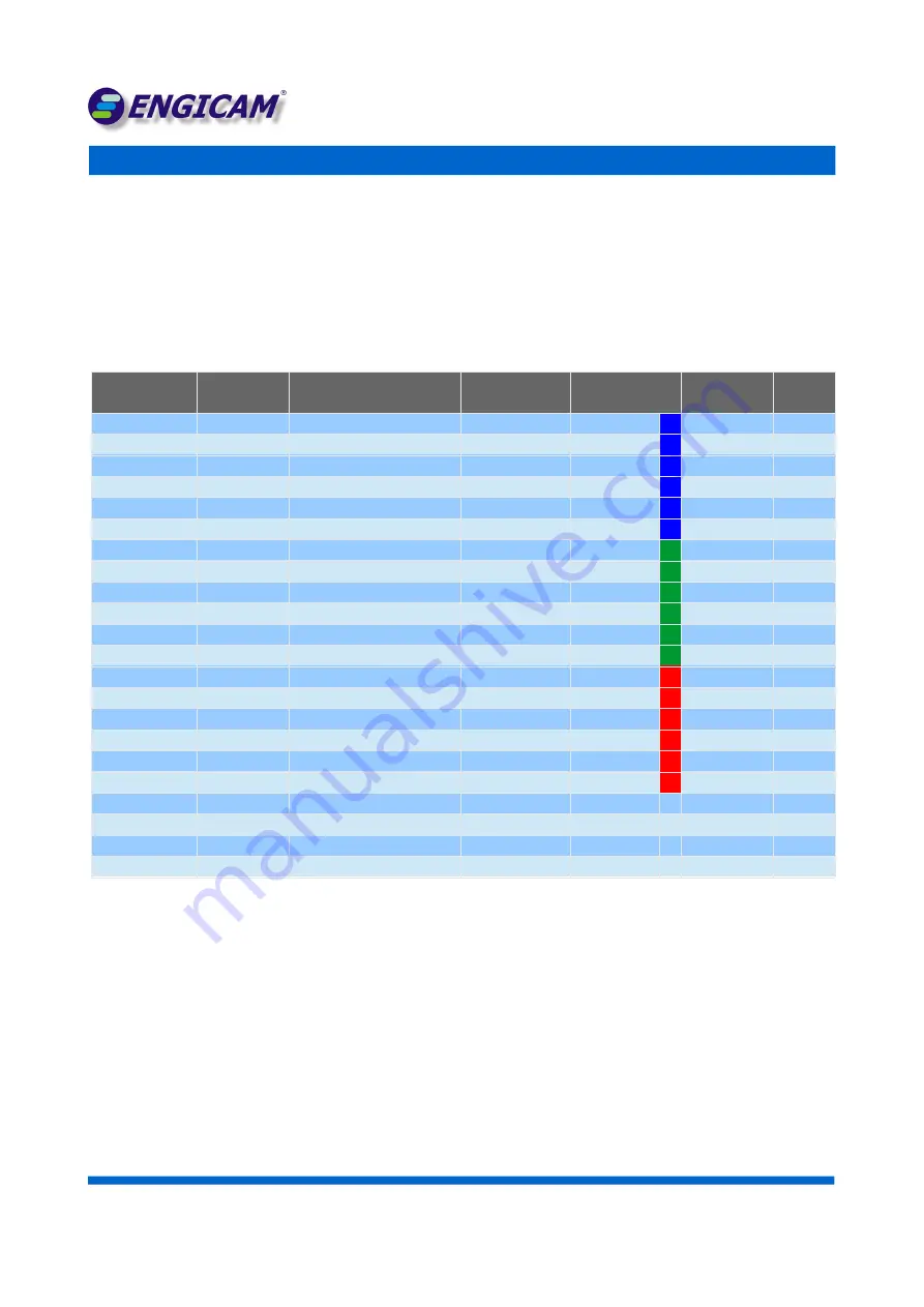
5.9.1 Connection map for 18 bit display
The following map represent the connection mode applied to 18 bit TFT display.
For every connection the colour controlled is joined
B Connector
Name
Primary Function
Description
CPU Pin Name
18 bit TFT
GPIO
Capable
Voltage
26
DISP0_D0
LCD interface
LCD_DAT00
BLU 0
Y
+3,3V
24
DISP0_D1
LCD interface
LCD_DAT01
BLU 1
Y
+3,3V
16
DISP0_D2
LCD interface
LCD_DAT02
BLU 2
Y
+3,3V
18
DISP0_D3
LCD interface
LCD_DAT03
BLU 3
Y
+3,3V
22
DISP0_D4
LCD interface
LCD_DAT04
BLU 4
Y
+3,3V
30
DISP0_D5
LCD interface
LCD_DAT05
BLU 5
Y
+3,3V
28
DISP0_D6
LCD interface
LCD_DAT06
GREEN 0
Y
+3,3V
36
DISP0_D7
LCD interface
LCD_DAT07
GREEN 1
Y
+3,3V
20
DISP0_D8
LCD interface
LCD_DAT08
GREEN 2
Y
+3,3V
14
DISP0_D9
LCD interface
LCD_DAT09
GREEN 3
Y
+3,3V
2
DISP0_D10
LCD interface
LCD_DAT10
GREEN 4
Y
+3,3V
6
DISP0_D11
LCD interface
LCD_DAT11
GREEN 5
Y
+3,3V
8
DISP0_D12
LCD interface
LCD_DAT12
RED 0
Y
+3,3V
10
DISP0_D13
LCD interface
LCD_DAT13
RED 1
Y
+3,3V
12
DISP0_D14
LCD interface
LCD_DAT14
RED 2
Y
+3,3V
4
DISP0_D15
LCD interface
LCD_DAT15
RED 3
Y
+3,3V
32
DISP0_D16
LCD interface
LCD_DAT16
RED 4
Y
+3,3V
34
DISP0_D17
LCD interface
LCD_DAT17
RED 5
Y
+3,3V
38
DISP0_HSYNC
LCD interface
LCD_HSYNC
Y
+3,3V
40
DISP0_VSYNC
LCD interface
LCD_VSYNC
Y
+3,3V
42
DISP0_DRDY
LCD interface
LCD_ENABLE
Y
+3,3V
44
DISP0_CLK
LCD interface
LCD_CLK
Y
+3,3V
Table 15
D N :
3 5


