5.3 How to connect two 3-wire RS232 serial port
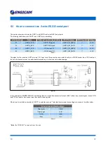
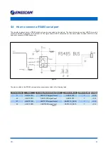
This section shows how to use the UART1 and UART5 as 3-wire RS232 serial ports.
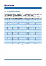
The following table shows the UART1 and UART5 pins numbering.
A Connector
Name
Primary Function Description
CPU Pin Name
GPIO Capable Voltage
75
UART5_TXD
UART TXD signal
UART5_TX_DATA
Y
+3,3V
73
UART5_RXD
UART RXD signal
UART5_RX_DATA
Y
+3,3V
28
UART1_TXD
OS Console TX
UART1_TX_DATA
Y
+3,3V
26
UART1_RXD
OS Console RX
UART1_RX_DATA
Y
+3,3V
Table 7
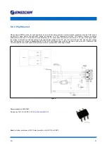
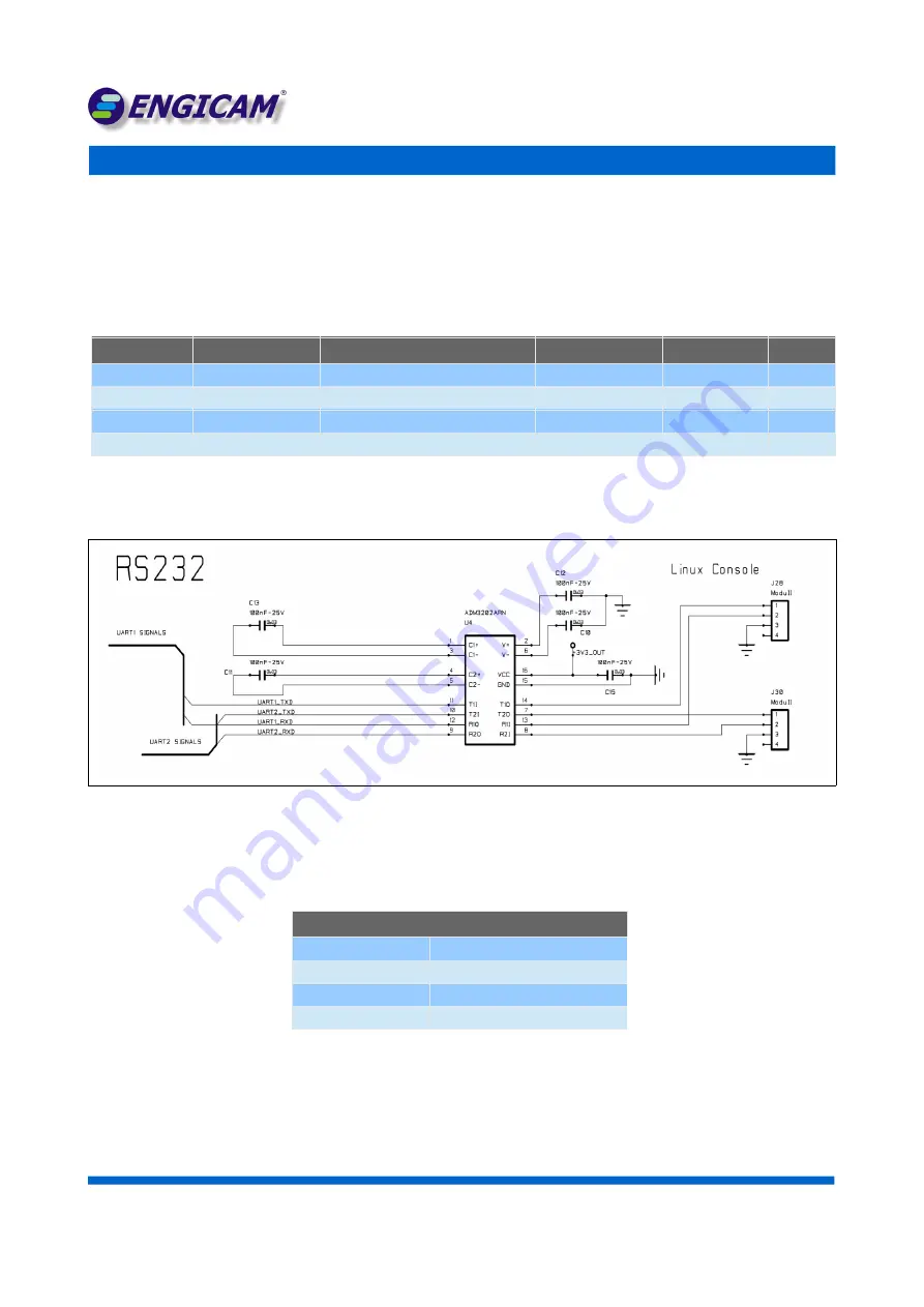
The signal on the module's UART pins are 3.3V logic level, this cannot be connected directly to a RS232 device like a PC Serial port,
the use of a transceivers on the base board is mandatory in order to avoid module damage.
Figure 4
In this example an ADM3202ARN IC from Analog Device is used like transceiver for both UART without any control signal. In case RTS
and CTS are need, a transceiver must be used for these signals.
When Linux is installed on a module, UART1 is used like console. The default communications settings are shown in the table below.
Linux console default settings
Baud rate
115200
Data length
8 bit
Parity
none
Stop
1bit
Table 8
*
Note
:
the CONUART is used as Linux Console
D N :
2 3


