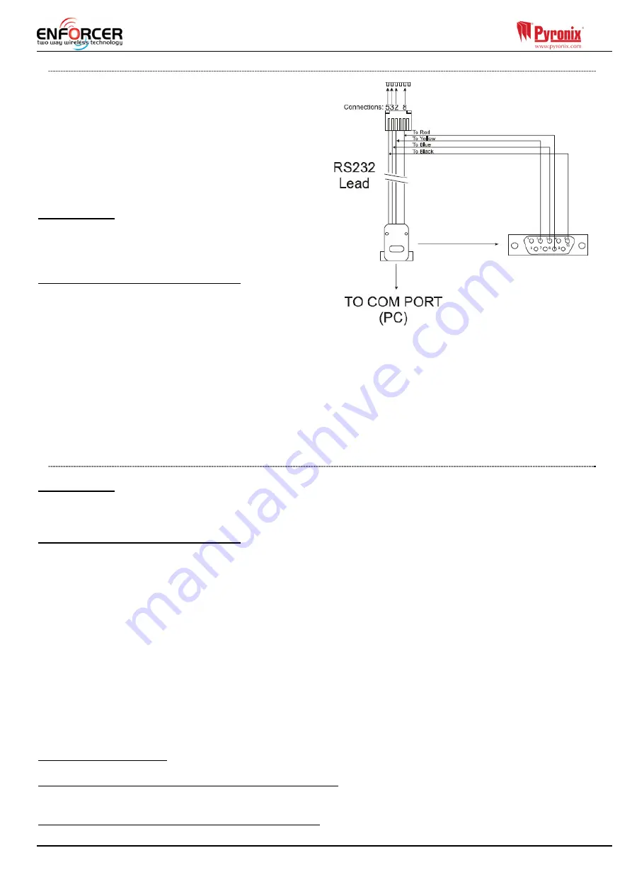
background image


Page: 

18


5.4.2


Serial Connection (RS232) 

The control panel is set up by the factory with 
RS232 port enabled as a method of connection to 

the UDL software. 

NOTE:

 For this connection it’s required to use a special 

cable that is supplied by Pyronix or can be created by 
using the diagram on the right. 

NOTE:

 If your PC does not have a serial port, you may 

require a standard RS-232 to USB converter. 

Unscrew and open the Enforcer Casing, plug the RS-
232 cable into the dedicated connector as shown on 
the image to the right.  

On the Panel 

1) Enter the Engineer menu (code 9999) 

2) Scroll the menu (X button) until the “Options 
Up/Downloading” 

3) Choose RS-232 in the “Download by” option 

On InSite UDL software from a PC 

1) To setup the COM port associated to “modem” 
open the software, click on “Configuration”, - choose 
“Modem Settings” and select “RS-232” option  

2) Make sure that the serial COM used by UDL is the 
same set in PC-> Device manager ->Ports 

3) Make sure that the UDL Graphic user interface RS-232 icon has turned green. 
4) Click on “Force Dial Customer” 

5) Set “Dial Mode” field to “RS-232” 
6) Enter the Engineer code in the “Engineer Code” field  

7) Click on “dial” 
8) If connection is successful, the RS-232 icon will become blue 

NOTE:

 If a Site Name is set up on the panel the UDL Site Name must be exactly the same (verbatim) 

otherwise the connection will not be possible.  

5.4.3


Modem Connection (DIGI 1200, PSTN) 

Ensure the panel / modem on the PC where UDL is installed are connected to a suitable PSTN line. 

On the Panel 

1) Enter the Engineer Menu (code 9999)  
2) Scroll the menu (X button) until the “Options Up/Downloading” 

3) Choose Modem in the “Download by” option 

On InSite UDL software from a PC 

1) To setup the COM port associated to “modem” open the software, click on “Configuration”, choose 

“Modem Settings” and select “MODEM” option 


2) Verify that COM port associated to “Modem” in Insite is the same set in ‘Device manager /Ports’. 

3) Verify that the modem Icon has turned green in the software Graphic User Interface 
4) In the “Configurations” menu choose the “Modem Type” from the drop down menu. This is the 

modem connected to the PC and used to call the panel 
5) Press “Load Default String” to program the right initialization string for the selected modem 

6) Click on “Force Dial customer” 
7) Set “Dial Mode” field to “MODEM” 
8) Insert the telephone number in “Telephone Number” field 

9) Enter the Engineer code in the “Engineer Code” field  
10) Click on “dial” 

11) If connection is successful, the modem Icon will become blue. 

NOTE:

 If a Site Name is set up on the panel the UDL Site Name must be exactly the same (verbatim) otherwise 

the connection will not be possible.  

T

he PSTN card (

DIGI-1200)

 fits inside the Enforcer 32WE and is used for the following operations: 

Send Alarms to the ARC: It is possible to send alarm events to the monitoring station via the Contact 

ID and SIA Level 1 and Level 3. 
Programming the panel remotely via the telephone line:


It is possible to program the Enforcer remotely 

via the telephone line. In order to be able to use this feature it is necessary that the telephone line 
used is a conventional analogue telephone line. 

Receive Automatic Remote Service calls and alarms:


It is possible to receive the RM service and alarm 

calls received by the UDL software installed on a PC and modem. 

Summary of Contents for RINS1708-3

Page 1: ...s a 100 dBA siren please be aware of this during installation EN50131 1 2006 A1 2009 EN50131 3 2009 EN50131 6 2008 EN50131 5 3 2005 A1 2008 Security Grade 2 Environmental Class II Software Version 10...

Page 2: ...Important Installation Notes 6 4 Technical Specification 7 5 Installation Guide 8 5 1 Wiring Peripherals to the RS485 Bus 9 5 2 Entry Control with the Internal Tag Reader 13 5 3 Entry Control with the...

Page 3: ...put Expanders Total Inputs Wireless Wired 66 On board outputs 3 User Automation Outputs 19 Outputs max 34 16 x 1 x Wired Output Exp 12 x 4 x Wired Input Exp 3 x Keypads Readers User Codes and Tags 75...

Page 4: ...ing the front of the Enforcer 32 WE as modems I O boards etc may be connected to the front 3 Rotate the front of the Enforcer 32 WE 180 degrees and hang it on the opening screws if required 3 1 Mains...

Page 5: ...if the Enforcer 32 WE is installed on an uneven surface 5 If an I O board is installed then this space is used to install it See page 9 3 3 Inside of the Enforcer 32 WE Front 1 RS232 connection for Up...

Page 6: ...cian Ensure that a readily accessible disconnect device is incorporated in the premises installation wiring and is provided external to the equipment with a contact separation of at least 3 0mm and co...

Page 7: ...A Continuous Load Comms Time 40mS 40ms Battery Type KF BATT CR1 3N KF4 MK2 Battery Type PIR BATT CR123A Battery Type UT BATT CR2 Environment All Devices Nominal operating temperature 10 C to 50 C Cert...

Page 8: ...nciples NOTE 1 No alarm system cable should be run with other cables carrying AC or digital signals NOTE 2 The cables should be protected by the use of grommets where appropriate NOTE For greater than...

Page 9: ...4 The maximum devices the I O board can have on the RS485 bus are as follows 4 x Input Expanders PCX RIX8i PCX RIX8 PCX RIX8 PSU 1 x Output Expander PCX ROX8R8T or PCX ROX16R PSU 4 x Keypads Readers s...

Page 10: ...cess control entry control please refer to page 13 5 1 4 Wiring External Readers If an additional external reader is connected this will need to be assigned in the programming of Assign Keypads Reader...

Page 11: ...cuit of the bell box Note that the input must be programmed as tamper The resistor value is 1K as shown in the diagram above IMPORTANT NOTE THE BELL BOX CONNECTED WILL NEED TO BE IN SCB self contained...

Page 12: ...using a PCX RIX8 PSU the D2 MUST NOT be connected RIX Address 0 Inputs 35 42 RIX Address 1 Inputs 43 50 RIX Address 2 Inputs 51 58 RIX Address 3 Inputs 59 66 5 1 8 Connecting an Output Expander 1 x Re...

Page 13: ...Page 13 5 2 Entry Control with the Internal Tag Reader 5 2 1 Connecting the Push to Exit Button Entry Control 5 2 2 Connecting the Mag Lock Control Entry Control...

Page 14: ...control panel and the door will lock The system will set after the final door is closed exit time expires 5 2 4 Disarming with Entry Control Action Visual Sequence Present a valid tag to the reader a...

Page 15: ...Page 15 5 3 Entry Control with the External Tag Reader 5 3 1 Connecting the Push to Exit Button Entry Control 5 3 2 Connecting the Mag Lock Control Entry Control...

Page 16: ...ill start on the control panel The RED LED will illuminate when the system has armed and after a few seconds the LED will extinguish 5 3 4 Disarming with Entry Control Action Visual Sequence Present a...

Page 17: ...tings have been entered for your network see Network Setup page 26 On InSite UDL software from a PC First of all once the software has opened go to the configuration tab and then select modem settings...

Page 18: ...Scroll the menu X button until the Options Up Downloading 3 Choose Modem in the Download by option On InSite UDL software from a PC 1 To setup the COM port associated to modem open the software click...

Page 19: ...a service or not as listed below Some networks provide the data channel as a standard service with pay as you go and contract SIM cards Some networks have to enable the data channel separately Some ne...

Page 20: ...o communicate over a Local Area Network to either InSite Pyronix Cloud or to an ARC NOTE The product has been approved as supplied If the communications module is replaced with a different model besid...

Page 21: ...nicate either via contact ID Fast Format SIA or SMS texts via a telephone line It will also enable remote uploading downloading Before making these connections all power must be disconnected from the...

Page 22: ...or Disarmed Mode Unset State may be relevant to a specific area Personal Attack PA Hold Up HU Bypass Inhibit Unused Isolated Bell External Sounder SAB External Warning Device self powered is assumed...

Page 23: ...Page 23 8 NOTES...

Page 24: ...ouse Braithwell Way Hellaby Rotherham S66 8QY Customer Support line UK Only 44 0 845 6434 999 local rate or 44 0 1709 535225 Hours 8 00am 6 30pm Monday to Friday Email customer support pyronix com Web...

Reviews: