Contents
1. SITTING ........................................................................................................................... 1
2. TECHNICAL SPECIFICATIONS ........................................................................................ 1
3. APPLICATION RANGE ................................................................................................... 2
4. WIND TURBINE ASSEMBLY ........................................................................................... 2
5. SYSTEM CONFIGURATIONS .......................................................................................... 3
6. DEBUG AND TEST .......................................................................................................... 5
7. MAINTENANCE .............................................................................................................. 6
8. TROUBLE SHOOTING .................................................................................................... 7
8. WIND AND SOLAR HYBRID CONTROLLER .................................................................. 9
Safety Instructions
1 Prevent winding overheating
For winds above the cutting speed the electromagnetic brake could be insufficient, and the equipment would work outside its
specifications.
It’s recommended to mechanically immobilize the equipment to avoid excessive winding overheating.
2 Notice: please comply with the following instructions before using the wind turbine.
2.1 Please read these instructions before use.
2.2 Safety installations
2.2.1 Install wind turbine in sunny day
2.2.2 Do not install wind turbine in windy day.
2.2.3 Wear wet gloves or clothes are prohibited.
2.2.4 Install and maintain wind turbine under professionals guidance, or contact distributor.
2.2.5 Do not use poor quality cables, use original cables as far as possible in order to avoid leakage or fires.
2.2.6 Do not open controller and inverter casing without professional guidance.
2.2.7 Install grounding device in accordance with application standard address installation instructions.
2.2.8 Battery may be sparks flying while wiring, make sure that no inflammables environment nearby.
2.2.9 Do not place the controller, inverter and battery in damp, rain, vibration, corrosion and strong electromag-
netic interference environment, the places in direct sunlight, near heater or the other heat sources are not allow,
either.
2.3 Selection and installation requirements of controller, battery.
2.3.1 Controller specification should be matched with voltage, power and current ofthe battery, solar panel, wind
turbine and load.
2.3.2 Controller and battery should be put in a power housing cabinet, and the housing is located in ventilated
place where people are not easy to touch.
2.3.3 Controller and battery must be installed in accordance with corresponding electric equipment installation
standard and operation regulations of manufacturer.
2.3.4 Use distribution cabinet and adoptsealed battery in living room.
2.3.5 Negative pole of battery should be in grounding.
2.4. The connection of each internal part should be fixed and reliable, plug and socket are not allowed.
2.4.1 The connection of each internal part should be fixed and reliable, plug and socket are notallowed.
2.4.2 The connection of system output and external circuit should be fixed, or system output use the socket.
2.4.3 Please don’t use the two-way plus to connect the output of system and outer circuit.
2.4.4 As for the installation of other circuit, all of it should be protected by the wire because it’s easy to damage
for the expose.
3 For your safety, please read these instruction carefully before installation or operation.
Summary of Contents for GE-600-24
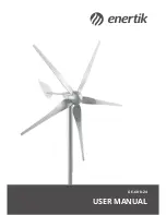
Page 1: ...GE 600 24 USER MANUAL...


