Enertech WS036 Installation & Operation Manual Download Page 22

Enertech Global, LLC

22

WS Rev. E Models

Installation and Operations Manual

Features

Enertech Global geothermal heat pump controls leverage a 

modular approach for controlling heat pump operation. The 

control system uses a combination of printed circuit boards, 

depending upon the features equipped in a particular unit. 

This approach simplifies installation and troubleshooting, and 

eliminates features that are not applicable for some units.

Microprocessor Features and Operations

Enertech Global geothermal heat pump controls provide a 

unique modular approach for controlling heat pump 

operation. The control system uses one, two, or three printed 

circuit boards, depending upon the features of a particular 

unit. This approach simplifies installation and troubleshooting, 

and eliminates features that are not applicable for some 

units. 

A microprocessor-based printed circuit board controls the 

inputs to the unit as well as outputs for status mode, faults, 

and diagnostics. A status LED and LED(s) for each fault are 

provided for diagnostics.

A removable low voltage terminal strip provides the 

necessary terminals for thermostat connections. Some 

models offer an additional removable terminal strip for 

accessory wiring connections.

Startup/Random Start

The unit will not operate until all the inputs and safety 

controls are checked for normal conditions. A ten to twenty 

second random start delay is added at power up and 

whenever a Y1 call is received. This avoids multiple units from 

being energized at the same time after power loss or other 

situations. 

Short Cycle Protection (ASC)

A built-in five minute anti-short cycle (ASC) timer provides 

short cycle protection of the compressor.

Component Sequencing Delays 

Components are sequenced and delayed for optimum space 

conditioning performance and to make any startup noise less 

noticeable. There is a short delay between the blower motor 

and the compressor start up.

Test Mode

The microprocessor control allows the technician to shorten 

timing delays for faster diagnostics by removing the TEST 

jumper located on the lockout board. It should be reinstalled 

for normal operation after testing. The status LED will not be 

illuminated during the TEST mode.

Resistance Heat Control

The resistance heat control module contains the appropriate 

high-voltage control relays. Low voltage control signals from 

the lockout board energize the relays in the resistance heat 

module to engage backup resistance heat when necessary. 

The lockout board offers a pass through W1 (1st Stage) and a 

relay output for W2 (2nd Stage). See staging in sequence of 

operation section. 

Loop Pump Circuit Breakers

The loop pump(s) and HWG pump are protected by control 

box mounted circuit breakers for easy wiring of pumps during 

installation. Circuit breakers eliminate the need to replace 

fuses.

Section 8: Controls

Safety Controls

The lockout board receives separate signals for high pressure, 

low pressure, low load heat exchanger freeze, source heat 

exchanger freeze, condensate overflow, and hot gas 

temperature limit faults. Upon a continuous 30-second 

measurement of all faults, except the high pressure fault, the 

compressor operation is suspended. The high pressure fault is 

immediate. The combination of LED(s) indicate each fault. 

Once the unit is locked out (see fault retry below), an output 

of 24VAC is energized on the “L” terminal for remote 

indication of a fault at the thermostat.

Flow Switch - FS (If equipped - brazed plate only)

.

A flow switch ensures the source water maintains the 

minimum required flow rate. This ensures that pumps are 

working and water connections remain intact. The flow 

switch will also trip when the source water begins to freeze, 

providing additional protection. A Flow Switch is utilized on 

units with a BPHE source coil. A Flow Switch is not included 

on units utilizing a COAX source coil.

Electronic Condensate Overflow Protection (CO)

(If equipped - Packaged Units Only)

The control board utilizes an impedance sensing liquid sensor 

at the top of the drain pan. When water touches the sensor, 

CO fault occurs. If the fault is present for 30 continuous 

seconds, the lockout board indicates a condensate overflow 

fault has occurred.

If water touches the condensate overflow sensor for 30 

continuous seconds, the compressor operation will be 

interrupted.  The control will go into fault retry mode. There 

is no delay of switch monitoring at startup.

Low Pressure-LP: 

If the low pressure switch is open 

continuously for 30 seconds, the compressor operation will 

be interrupted, and the control will go into fault retry mode. 

At startup, the low pressure switch is not monitored for 30 

seconds to avoid nuisance faults. (If the low pressure switch is 

open before startup then the unit will not start upon 

receiving an Y1 call and will lock out instead.)

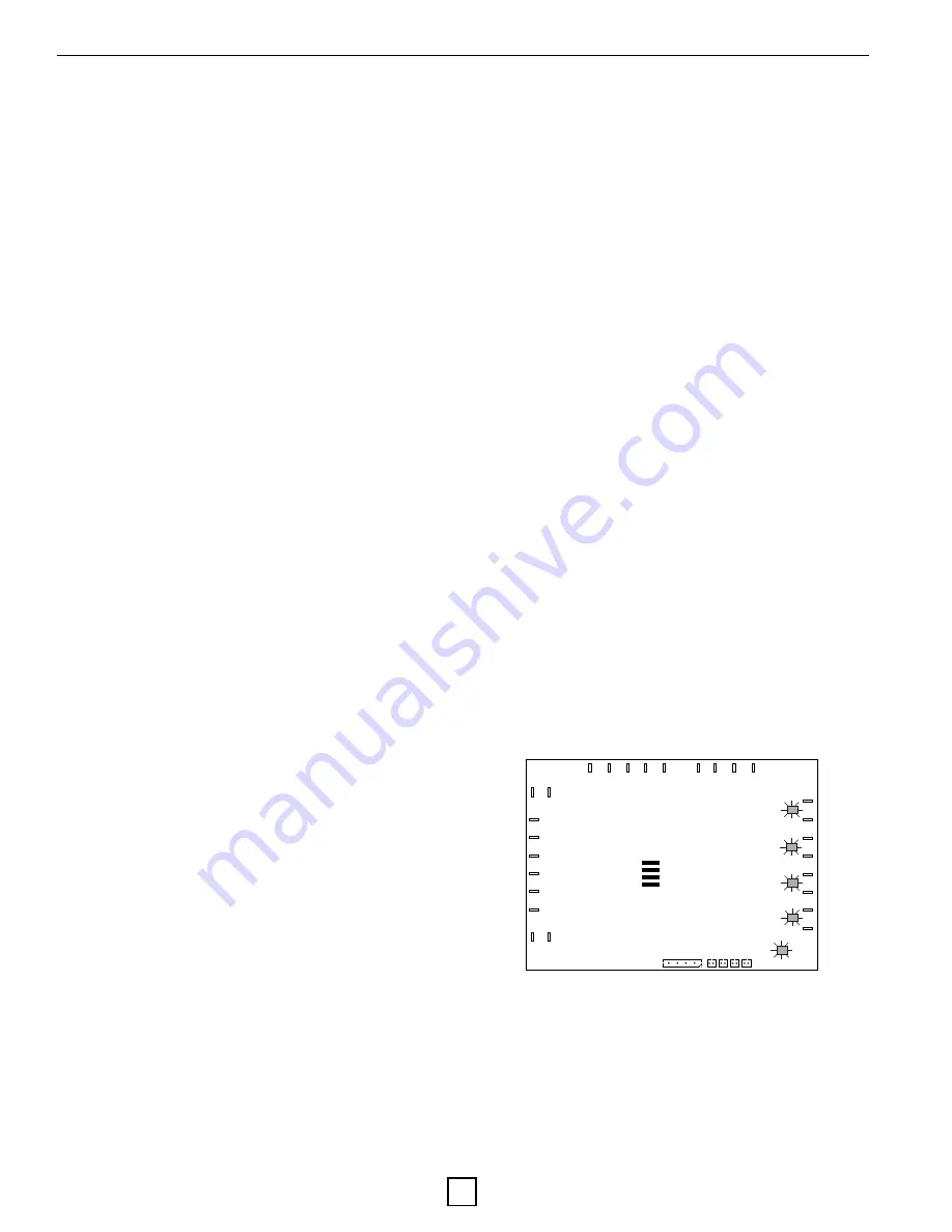
Lockout Board Layout

CC

HP

Lockout

Board

HWG  W2      G     W1    Y2           R_2   R_1  C_2  C_1

AFRZ

TEST

O/V

STATUS

LP

FS

CO

A

C

R

Y1

L

O     O

CCG

1

CCG

UART           1    2    3   4

FSW

High Pressure-HP: 

If the high pressure switch opens, the 

compressor operation will be interrupted, and the control will 

go into fault retry mode. There is no delay between the time 

the switch opens and the board entering into fault retry 

mode. There is also no delay of switch monitoring at startup. 

(If the high pressure switch is open before startup then the 

unit will not start upon receiving an Y1 call and will lock out 

instead.)

Summary of Contents for WS036

Page 1: ...Installation OperationsManual WS MODELS WATER TO WATER HEAT PUMPS HYDRONIC AIR HANDLERS 20D817 21NN 20D817 21NN...

Page 2: ...nection 16 Section 6 Antifreeze Antifreeze Overview 17 Pipe Fluid Volume Table 18 Antifreeze Percentages by Volume Table 18 Antifreeze Specific Gravity Table 18 Section 7 Desuperheater Installation De...

Page 3: ...Parameters 37 Pressure Drop Tables 38 Section 12 Troubleshooting Troubleshooting Tips 39 Troubleshooting Tips 40 Compressor Troubleshooting Tips 41 Refrigeration Troubleshooting Table 42 Superheat Su...

Page 4: ...e S Single Stage Unit Capacity Nominal MBTUH 036 048 060 072 084 Revision E Current Revision Voltage 1 208 230V 60Hz 1Ph Residen al 0 208 230V 60Hz 1Ph Commercial 2 208 230V 60Hz 3Ph Commercial 3 460V...

Page 5: ...ts Use caution to not damaged the finished surface of the unit Keep all cardboard or other packaging material for safe storage and transport to the job site prior to installation Remove the front serv...

Page 6: ...TION WILL VOID ALL WARRANTIES Consumer Instructions Dealer should instruct the consumer in proper operation maintenance filter replacements thermostat and indicator lights Also provide the consumer wi...

Page 7: ...the job site Pre Installation Before you fully install the geothermal equipment it is recommended you do the following Fully inspect the unit after unpacking Locate the Unit Start Up form from this ma...

Page 8: ...ter of 120 F the loop would have to maintain 35 F to operate within the acceptable operating conditions for the compressor Once your loop temperatures drop below 35 F the acceptable leaving load tempe...

Page 9: ...Enertech Global LLC 9 WS Rev E Models Installation and Operations Manual Unit Dimensional Data Section 4 Unit Data Information...

Page 10: ...5 60 01 208 230 1 178 0 30 8 0 5 0 0 31 3 39 0 70 10 208 230 1 178 0 30 8 0 0 5 5 36 3 44 0 70 11 208 230 1 178 0 30 8 0 5 5 5 36 8 44 5 70 20 208 230 3 136 0 19 6 0 0 0 0 19 6 24 5 40 21 208 230 3 13...

Page 11: ...the internal parts are two of the potential problems The Department of Natural Resources or your local municipality can direct you to the proper testing agency See Water Quality Table for guidelines W...

Page 12: ...ng materials HDPE copper brass or rubber hose hose kit only Typical Single Compressor Unit Piping Connection The following drawings indicate typical GSHP connections Please refer to product dimensiona...

Page 13: ...ill a closed system where the fluid will not evaporate If the earth loop header is external the loop system will still need to be flushed with a purge cart The non pressurized flow center needs to be...

Page 14: ...izontal position Acceptable mounting positions for Flo Link and GPM series flow centers Equally important to pump longevity is terminal box orientation See Acceptable terminal box locations for UPS26...

Page 15: ...t lowered water flow too much and essentially taken the flow regulator out of the equation It s a good idea to remove the ball valve handles once the system is completed to avoid nuisance service call...

Page 16: ...ule Wiring Schematic provides a layout of the board The module must be mounted in a NEMA enclosure or inside the unit control box Local code supersedes any recommendations in this document DC Bridge L...

Page 17: ...e and is mid to low price The biggest down side is that it is flammable in concentrations greater than 25 Ethanol Grain alcohol which by the ATF Alcohol Tobacco Firearms department of the U S governme...

Page 18: ...eeze solutions are shown in pure form not premixed Concentrations below 25 30 consult manufacturer typically require additional inhibitors 0 9600 0 9700 0 9800 0 9900 1 0000 1 0100 1 0200 1 0300 1 040...

Page 19: ...ng from water heater 5 Thread the MPT x 3 1 2 nipple into the water heater drain port Use Teflon tape or pipe dope on threads 6 Thread the center port of the brass tee to the other end of the nipple 7...

Page 20: ...ter Tank Brass Tee Adapter to Unit Water Line Drain Copper Tee For Domestic Cold Water In Line WARNING TO AVOID SERIOUS INJURY IT IS RECOMMENDED THAT AN ANTI SCALD MIXING VALVE IS INSTALLED ON THE HOT...

Page 21: ...r actual fitting and port locations Section 7 Desuperheater Installation Air Vent Locatedat System High Point Desuperheater Out Desuperheater In Heat Pump ColdWater Supply Hot Water Water Heater orSto...

Page 22: ...ence of operation section Loop Pump Circuit Breakers The loop pump s and HWG pump are protected by control box mounted circuit breakers for easy wiring of pumps during installation Circuit breakers el...

Page 23: ...perature T2 is higher than 220 F the HWG pump will be de energized All of the issues above will break the circuit of the HWG pump via the HWG signal from the lockout board and will not lockout the com...

Page 24: ...N ON FLASH ON JUMPER FS A FRZ TEST O V NOTES 2 WHEN THE TEST JUMPER IS PULLED GREEN STATUS LED WILL BE OFF 5 NOT ALL MODELS HAVE THIS FEATURE 6 THIS FAULT INDICATES A BAD SENSOR OPEN SHORTED OR DISCON...

Page 25: ...n status light blinking Over Under Voltage Disable O U When the O U jumper is installed the over under voltage feature is active When the jumper is removed the over under voltage feature is disabled O...

Page 26: ...Enertech Global LLC 26 WS Rev E Models Installation and Operations Manual Section 10 WS Wiring Diagram WS 036 084 Wiring Diagram...

Page 27: ...ct voltage Orange Black 230V Red Black 208V Correct any possible voltage drops in the main voltage 3 Set the thermostat to Heat or Cool Adjust set point to energize the unit System will energize after...

Page 28: ...ater Pressure In Source Water Pressure Out Source Water Pressure Drop F F F F F F Heat of Rejection Extraction BTU HR BTU HR F F F F F F Cooling Heating F F F F F F Heating F F F Heating V A GA A Sour...

Page 29: ...ischarge Suction Subcooling Superheat Source Water Temp Rise Load Water Temp Drop F GPM Ton GPM Ton F PSIG PSIG F F F F 40 173 242 68 104 12 28 5 16 13 19 4 9 45 173 242 75 110 12 28 5 15 14 20 4 9 50...

Page 30: ...3 1 7 2 17 3 4 7 8 3 4 7 8 18 4 1 9 5 4 1 9 5 12 1 6 3 7 6 2 14 3 1 6 3 7 14 1 8 4 2 6 2 14 3 1 8 4 2 15 1 9 4 4 7 8 18 0 1 9 4 4 16 2 1 4 8 8 2 18 9 2 1 4 8 18 2 5 5 8 2 5 5 8 19 2 7 6 2 2 7 6 2 20...

Page 31: ...ove the FS jumper see Controls Section for location and jumper the two FS terminals located between blue and violet wires on the right side of the board together to complete the flow switch circuit De...

Page 32: ...ge the valve Always use dry nitrogen when brazing Replace filter drier any time the circuit is opened Heat pump will not cool but will heat Heat pump will not heat but will cool Reversing valve does n...

Page 33: ...s Check contactor and 24 Volt coil Check capacitor connections check capacitor with capacitor tester If ohm meter reads 0 short resistance from C to S S to R R to C or from anyone of one of these term...

Page 34: ...14 8 14 10 16 10 16 19 24 19 24 18 22 9 12 Superheat Subcooling Conditions Typical R 410A Unit Superheat Subcooling Values Refrigeration Troubleshooting Table Condition Mode Discharge Pressure Suction...

Page 35: ...__________________________________________________________ City _____________________________State Prov __________ Email ___________________________________________ Application Residential New Constru...

Page 36: ...Enertech Global LLC 36 WS Rev E Models Installation and Operations Manual This page left blank for Warranty Form detachment...

Page 37: ...Enertech Global LLC 37 WS Rev E Models Installation and Operations Manual Revision Table Date Description of Revision Page 04MAR2022 IOM and Wiring Diagram updated ALL Section 14 Revision Table...

Page 38: ...Enertech Global LLC 38 WS Rev E Models Installation and Operations Manual This page intentionally left blank...

Page 39: ...Enertech Global LLC 39 WS Rev E Models Installation and Operations Manual This page intentionally left blank...

Page 40: ...e most up to date information please visit our website or contact our Customer Service department at info enertechgeo com Statements and other information contained herein are not express warranties a...

Reviews: