background image

5

5.0  ASSEMBLY AND SETUP

5.1  Important Receiving Instructions

Visually inspect all components for shipping damage. Shipping 

damage is not covered by warranty. If shipping damage is found, 

notify carrier at once. The carrier is responsible for all repair and 

replacement costs resulting from damage in shipment.


NOTICE

The jack rear access cover must be removed to gain 

access to various components and service items discussed in 

sections 5.2 through 5.4. Refer to Section 7.1 for cover removal 

instructions.

5.2  Hydraulic Oil Level

Before using the jack or connecting the air supply, remove the 

oil fill plug from the hydraulic reservoir and check the oil level. 

Add  additional  hydraulic  oil  to  reservoir  if  oil  level  is  low.  See 

Section 7.3 for oil level diagram, oil specifications and additional 

instructions.

5.3  Compressed Air Requirements

The compressed air system used with the jack must be capable 
of providing 80 - 100 psi [5,5 - 6,9 bar] @ 130 CFM [3681 l/min]. 
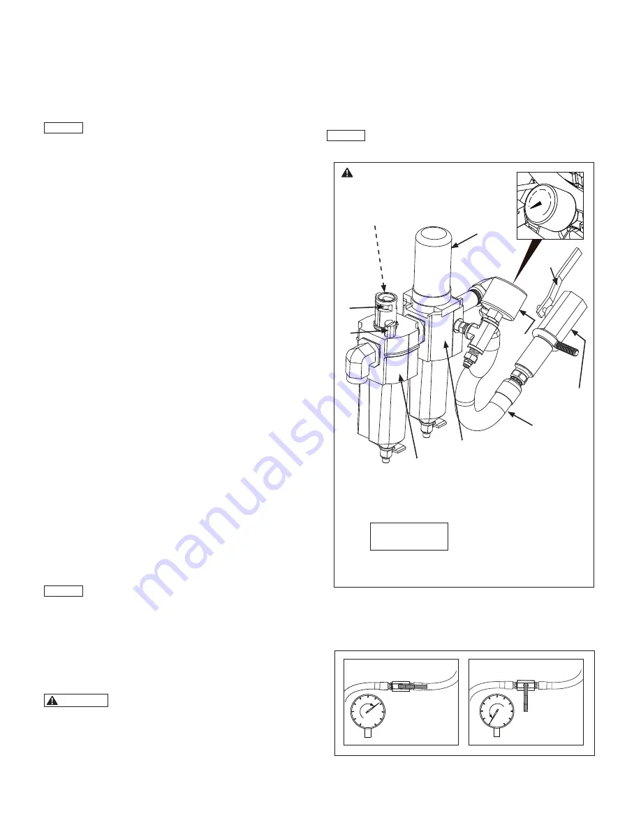
The jack is equipped with an air filter/regulator assembly, which 

consists of an air regulator, pressure gauge and moisture trap. 
See Figure 3, items B, I and J.
A short hose connects the filter/regulator to the air-shuto

ff

 valve. 

The  air  inlet  connection  is  a  1/2  inch  NPT  female  thread.  See 
Figure 3, items K, L and M. Refer to Figure 4 for shut-o

ff

 valve 

positions.
For  e

ffi

ciency  of  output  and  reliable  operation,  an  air  supply 

line  of  not  less  than  0.82  inch  [20,8  mm]  internal  diameter  is 

recommended. (Nominal Pipe Size - 3/4 inch pipe).
Check  the  air  pressure  gauge  with  the  pendant  UP  button 

depressed and the jack air motor running. Be sure there is NO 

load on the cylinder. This will provide an accurate dynamic air 
pressure reading.
The minimum dynamic air pressure required to operate the jack 
will vary, but is typically about 50 to 60 psi [3,4 - 4,1 bar].
Approximately 90 to 100 psi [6,2 to 6,9 bar] dynamic air pressure 
will be needed for the jack to achieve its rated 200 ton [1779 kN] 
lifting capacity.
Lifting speed and torque can be adjusted using the knob located 

at  the  top  of  the  filter/regulator.  To  prevent  damage  to  jack 

pneumatic components, the regulator air pressure setting should 

not exceed 120 psi [8,3 bar].


NOTICE

Pressure settings of above 120 psi [8,3 bar] will result 

in  reduced  air  motor  life  and  will  void  the  Enerpac  product 

warranty.

5.4  Air Lubrication

The  jack  pneumatic  system  is  equipped  with  an  automatic  air 

line lubricator. See Figure 3, items A, F, G and H. Lubricated air 

is  necessary  to  provide  lubrication  for  the  air  motor  and  to  help 

prevent rust formation.

  WARNING

Be certain that regulator air pressure gauge 

indicates zero (0) psi/bar before removing lubricator fill plug. 

Lubricant may spray from fill opening if fill plug is removed 

while  system  is  pressurized,  even  when  air  hose  has  been 

disconnected and air shut-o

ff

 valve is in the closed position. 

Serious eye injury and/or skin penetration could result. If any 

pressure  is  indicated,  relieve  pressure  as  described  in 

Section 7.2 of this manual.

Before using the jack, check the lubricant level in the sight gauge 

on the air line lubricator. Add additional lubricant if low. Refer to 

Section 7.6 for air lubricant recommendations and additional air 

lubricator information.
After  the  air  supply  hose  has  been  connected,  observe  the  oil 

flow through the oil drip window while the cylinder is in motion. 

Verify  that  the  lubricator  drip  speed  is  set  at  4  to  5  drops  per 

minute.


NOTICE

Air  motor  must  be  running  and  cylinder  must  be 

moving up or down when checking lubricator oil drip speed.

0

Figure 4, Air Shut-Off Valve Positions

OPEN

CLOSED


NOTICE:


NOTICE

  CAUTION

  WARNING

  DANGER

Be sure air pressure gauge (item J) 

indicates zero (0) psi/bar before 

removing lubricator fill plug (item F).

           Figure 3,   Filter/Regulator, Air Line Lubricator 

and Air Shut-off Valve

I

M

K

L

B

H

A

J

F

G

Key:

  A.  Air Line Lubricator
  B. Air Filter/Regulator 

    (with moisture trap)

  F.  Lubricator Fill Plug
  G  Oil Drip Window

  H. Oil Drip Speed Control 

    (inside oil drip housing) 

  I.  Air Regulator Knob
  J.  Air Pressure Gauge
  K.  Air Inlet Hose
  L.  Air Inlet Connection 

    (1/2 inch NPT)
  M. Air-shuto

ff

 Valve

Note:

 See Fig. 13 

for items C, D and E.

Summary of Contents for Pow'R-LOCK PL200 Series

Page 1: ...word 1 2 Use Guidelines Supplement A copy of the Pow R Lock Use Guidelines Supplement Enerpac document L4131 has been packed separately with the jack Read and fully understand the instructions and pre...

Page 2: ...ON Failure to observe and comply with the following precautions could result in minor or moderate personal injury Property damage could also occur When jack is not in use fully retract the cylinder an...

Page 3: ...599 A2 C A1 E2 E1 D H B G F B E2 C H E2 E1 G F D A2 A1 Table 3 External Dimensions PL20025 ASA A1 A2 B C D E1 E2 F G H inch mm inch mm inch mm inch mm inch mm inch mm inch mm inch mm inch mm inch mm...

Page 4: ...Enerpac declares that this product has been tested and conforms to applicable standards and is approved to carry the CE mark An EU Declaration of Conformity is enclosed separately 05 08 09 08 07 10 0...

Page 5: ...fting speed and torque can be adjusted using the knob located at the top of the filter regulator To prevent damage to jack pneumatic components the regulator air pressure setting should not exceed 120...

Page 6: ...ow be tilted back onto the wheels and pushed or pulled to the work area CAUTION Do not walk backwards while pulling the jack Always look toward the direction where the jack is being pulled Failure to...

Page 7: ...d while it is being supported by the jack The load may become unstable and fall Do not use the jack outdoors in windy conditions Changes in wind direction or velocity could cause the load to become un...

Page 8: ...ground below must not exceed 1 4 inch 6 4 mm If additional settling occurs lower the load and reposition jack on solid ground 6 5 1 BEFORE BEGINNING THE LIFT 1 Using the handle assembly adjust the ja...

Page 9: ...tem depress and hold the pendant UP button The air motor may run for a few seconds but will stop when pressure is relieved 3 Always store the jack and its accessories in a clean and dry area free of m...

Page 10: ...Be especially careful to avoid off center loads and side loads when using extensions and spacers Table 6 Maximum Additional Stack Height Using optional PLB and PLE Series extensions and PLS Series sp...

Page 11: ...he cylinder Release the UP button IMMEDIATELY when the cylinder starts advancing usually after about 1 or 2 seconds This procedure will relieve any trapped pressure in the jack hydraulic system NOTICE...

Page 12: ...llons 18 9 liter of oil when filled to the proper level with cylinder fully retracted and air motor off Dispose of used oil in accordance with all applicable laws and regulations 4 Loosen and remove o...

Page 13: ...line lubricant bowl The lubricant level should be at least 1 2 full NOTICE If lubricant level is low add additional lubricant as described in steps 3 through 6 If lubricant level is OK skip these ste...

Page 14: ...ure Each tire should be inflated to 90 psi 6 2 bar Inspect the caster wheels for damage Remove any loose dirt Check that each caster wheel rotates and pivots freely and that mounting hardware is prope...

Page 15: ...ction and lubrication tasks See Figure 19 Remove any loose dirt or debris from the chain drive assembly Check each chain tensioner to verify that it is applying firm spring tension against the chain I...

Page 16: ...onnect the air supply hose and move the air shutoff valve to the OPEN position WARNING In the following step it will be necessary to extend and retract the cylinder several times Stay clear of the cyl...

Page 17: ...essure requirements d Clogged or blocked pump intake screen Have hydraulic reservoir and intake screen flushed and cleaned by Enerpac Authorized Service Center e Pneumatic control circuit components l...

Page 18: ...all amount before retraction begins This is normal operation a Insufficient compressed air pressure or volume Check air pressure at filter regulator Increase regulator setting if pressure shown on gau...

Page 19: ...e chain as required Determine if other problems may have caused drive chain wear or failure c Lock nut drive components are worn or loose Have Enerpac Authorized Service Center inspect condition of lo...

Page 20: ...______________________________________________________________________ _______________________________________________________________________________________ _________________________________________...

Page 21: ...______________________________________________________________________ _______________________________________________________________________________________ _________________________________________...

Page 22: ...______________________________________________________________________ _______________________________________________________________________________________ _________________________________________...

Page 23: ...______________________________________________________________________ _______________________________________________________________________________________ _________________________________________...

Page 24: ...Kong and Taiwan Actuant Asia Pte Ltd 83 Joo Koon Circle Singapore 629109 T 65 68 63 0611 F 65 64 84 5669 sales sg enerpac com South Korea Actuant Korea Ltd 3Ba 717 Shihwa Industrial Complex Jungwang...

Reviews: