background image

L4478_a

19

•  Reassembly and Installation 

In the following steps, coat all O-rings and 

seals with silicone grease before installation.

Do not use excessive force when installing 

the piston rod (3) in the following steps. Excessive force 

may cause damage to these component and also may 

damage the sealing faces within the wrench.

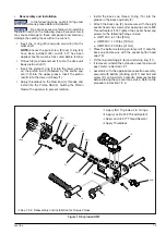
•  Insert the O-ring (20) and grub screw (8) into the 

relief shaft.

NOTE:

 Ensure the grub screw (8) and O-ring (20) 

have been installed after Loctite 577 has been 

applied. Loctite must be fully cured before testing.

•  Fit bush (5) and rod end seal (14) into the drive unit 

body piston shaft (1)

•  Insert the piston O-ring (16) into the lower groove 

on the piston rod (3) followed by the piston cup 

seal (13) into the upper groove. Insert the piston 

rod (3) into the drive unit body (1).

•  Apply threadlock to the Rod End (4) threads and 

install into the Piston Rod (3), holding the Piston 

Rod with a spanner to prevent rotation.


NOTICE


NOTICE

8

20

16

13

15

2

18

17

14

5

11

4

6

12

3

10

✽⁂

1

7

9

19


Apply ISO 10 grade oil to O-rings.


Apply Loctite 243 Thread Sealant

 Apply Loctite 577 Thread Sealant

 Apply Threadlock

•  Install the back cap thread O-ring (15) into the 

groove in the back cap body (2).

•  Attach the back cap (2), and secure with the eight 

socket head cap screws after applying Loctite 243 

Thread Sealant (10).


Tighten the socket head cap 

screws to the following Torque values:


ο HMT1500 : 6 Ft/lbs [8 Nm]


ο HMT3500 : 14 Ft/lbs [19 Nm]


ο HMT7500 : 30 Ft/lbs [41 Nm]

•  Place the bottom retaining pin lanyard (17) onto the 

back cap and secure with the socket button head 

cap (18).

•  Fit the top retaining pin (6) and retaining ring (11).
•  If removed, reinstall the hydraulic swivel and swivel 

post. Refer to Section 7.2.1.

•  Assembly with the appropriate cassette assembly, 

secured with bottom retaining pin (11) and ball end 

screw (9); and perform hydraulic pressure testing 

before placing the wrench into service. Refer to the 

procedure in Section 7.2.6. 

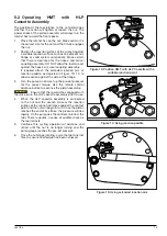
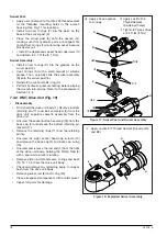
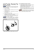
Figure 19: Exploded HMT

⁂•

See 7.3.2, Reassembly and Installation for Torque Values.

Summary of Contents for HMT Series

Page 1: ...ment Revision A Document Revision Date 25 AUG 2020 Document Language ENGLISH EN Operation and Maintenance Manual HMT Modular Tool Enerpac HMT To reduce the risk of injury user must read and understand...

Page 2: ......

Page 3: ...AMEPLATE AVAILABLE LANGUAGES L4478 is available in the following languages visit www enerpac com for a copy Weitere Sprachen finden Sie unter www enerpac com Para otros idiomas visite www enerpac com...

Page 4: ...1 HMT WITH HLP CASSETTE DIMENSIONAL CALLOUT ART 12 4 2 HMT WITH HLP CASSETTE DIMENSIONAL TABLE 12 4 3 HMT WITH HSQ CASSETTE DIMENSIONAL CALLOUT ART 13 4 4 HMT WITH HSQ CASSETTE DIMENSIONAL TABLE 13 5...

Page 5: ...raulic pressure If the couplings are not fully connected oil flow will be blocked and the wrench could be subjected to excessive hydraulic pressures Catastrophic failure of wrench could result WARNING...

Page 6: ...e of the fastener being loosened or tightened Failure to observe this precaution can result in the wrench becoming unstable and can lead to catastrophic failure of the tool CAUTION Always position the...

Page 7: ...an incendiary spark that may be caused by the impact of aluminium components with corroded steel However to reduce the chance of an incendiary spark use of the wrench with corroded steel structures o...

Page 8: ...es Part 1 Basic method and requirements and also the draft standard of ISO IEC 80079 36 Contact Enerpac if there are any questions regarding the ATEX classification or questions regarding application...

Page 9: ...HMT HLP Low Profile Cassette 1 2 3 4 5 6 7 8 1 Swivel Adaptor Hose Connections 2 Wrench Body 3 Fixed Pin 4 Rod End 5 Bottom Retaining Pin 6 Lanyard 7 Handle 8 Back Cap 1 6 2 4 5 7 3 8 1 3 4 5 6 2 1 Fr...

Page 10: ...Drive Cassette Body 2 Drive Pin 3 Body Spacer 4 Drive Plate 5 Reaction Arm Spline 6 Reaction Arm Set Screw 7 Square Drive 8 Reaction Arm 9 Retaining Ring 10 Link Pin Assembly 11 Link Pin Assembly Lany...

Page 11: ...rench body and drive plate assembly drive pin prior to operation will damage the rod end Resulting damage will not be covered under warranty 3 2 3 Using Extended Reaction Arm Reaction Paddle with the...

Page 12: ...end Resulting damage will not be covered under warranty 3 2 5 Selecting HSQ Cassette Direction The following diagram illustrates the direction the square drive should face for loosening and tightenin...

Page 13: ...engaged and screwed snugly together NEVER use an even number of hydraulic twin hoses between the pump and wrench If so you have the high pressure on the retract side and your wrench is not able to wo...

Page 14: ...80 1 025 Maximum Torque lbf ft 1 541 3 543 7 562 Nm 2 089 4 804 10 252 Weight Cassette lbs 4 41 8 82 11 02 17 63 19 84 kg 2 0 4 0 5 0 8 0 9 0 HMT lbs 2 2 3 97 7 05 kg 1 0 1 8 3 2 Dimensions A inch mm...

Page 15: ...09 480 1 025 Maximum Torque lbf ft 1 541 3 543 7 562 Nm 2 089 4 804 10 252 Weight HSQ lbs 5 95 9 04 18 08 kg 2 7 4 1 8 2 HMT lbs 2 2 3 97 7 05 kg 1 0 1 8 3 2 Dimensions A inch mm 7 28 184 83 8 36 212...

Page 16: ...he nut or bolt on the opposite end in place is correctly positioned and secured Be certain that backup wrench is of the correct size and that there is an adequate abutment surface Personal injury coul...

Page 17: ...ange 3 Turn the pump on and set up the pre set pressure for the correct torque Use the remote control advance button to advance the piston assembly Ensure that the rod end has engaged with the drive p...

Page 18: ...is connected to the nut and the wrench started the reaction surface of the wrench will move against the contact point and the nut will begin to turn Once the piston reaches the end of its stroke the...

Page 19: ...urns beyond finger tight To allow the sealant sufficient time to cure wait a minimum period of 3 hours at 68 to 104 F 20 to 40 C or 6 hours at 40 to 68 F 5 to 20 C before pressurizing the wrench NOTIC...

Page 20: ...unit body 1 Remove bottom retaining pin 11 and ball end screw 9 from the drive unit separate cassette assembly from the drive unit Unscrew the socket button head cap 18 from the back cap 2 and remove...

Page 21: ...panner to prevent rotation NOTICE NOTICE 8 20 16 13 15 2 18 17 14 5 11 4 6 12 3 10 1 7 9 19 Apply ISO 10 grade oil to O rings Apply Loctite 243 Thread Sealant Apply Loctite 577 Thread Sealant Apply Th...

Page 22: ...22 23 To separate the square drive reaction arm 4 unscrew the securing reaction arm grub screw 20 and disengage Remove the square drive circlip 8 and slide the reaction arm spline 3 off the square dri...

Page 23: ...LP2 LP3 LP1 LP5 LP6 LP7 LP8 LP4 LP10 LP11 LP12 LP13 LP9 molybdenum disulphide grease Lubrication Points Molybdenum Disulphide Grease LP1 Pawl All Surfaces LP6 Inner Surface LP10 Inner Surface LP2 Bear...

Page 24: ...LP2 LP3 LP2 LP4 LP7 LP7 LP8 LP6 LP5 LP10 LP9 LP1 LP12 LP11 molybdenum disulphide grease Lubrication Points Molybdenum Disulphide Grease LP1 Pawl All Surfaces LP5 Internal Bearing LP9 Bearing Surface...

Page 25: ...grease in the areas shown in Figure 23 If a fault develops with the retaining button assembly 16 the whole assembly will need to be replaced It is not recommended that this item be disassembled Figure...

Page 26: ...ms marked supplied in Top Retaining Pin Kit HMT1500TRK HMT3500TRK HMT7500TRK Items marked supplied in Bottom Retaining Pin Kit HMT1500BRK HMT3500BRK HMT7500BRK Items marked supplied in Grub Screw Kit...

Page 27: ...Kit not shown TSP300MKA TSP300MKA TSP300MKA 13 Piston Cup Seal 1 14 Rod End Seal 1 15 Back Cap O Ring 1 16 Piston O Ring 1 17 Lanyard 1 18 Screw 1 19 Handle 1 SWH6A SWH6A SWH6A 20 O Ring 1 Indicates...

Page 28: ...MT HLP Cassette Service Kits Items marked supplied in Drive Plate Kit see 8 4 1 8 4 3 HMT HLP Cassette Service Kits Items marked supplied in Ratchet Kit see 8 4 1 8 4 3 HMT HLP Cassette Service Kits I...

Page 29: ...as part of Side Plate Kit see 8 4 1 8 4 2 8 4 3 HMT HLP Cassette Service Kits Indicates items included and available only as part of Drive Plate Kit see 8 4 1 8 4 2 8 4 3 HMT HLP Cassette Service Kit...

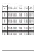
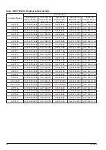
Page 30: ...4 04 HLP1109 HLP1500175111 HLP1111DPK HLP1109RK HLP1105WPK HLP1500 14 04 HLP1110 HLP1500175111 HLP1111DPK HLP1110RK HLP1105WPK HLP1500 14 04 HLP1111 HLP1500175111 HLP1111DPK HLP1111RK HLP1105WPK HLP15...

Page 31: ...4 04 HLP3201 HLP3500175201 HLP3201DPK HLP3201RK HLP3204WPK HLP3500 14 04 HLP3202 HLP3500175204 HLP3204DPK HLP3202RK HLP3204WPK HLP3500 14 05 HLP3203 HLP3500175204 HLP3204DPK HLP3203RK HLP3204WPK HLP35...

Page 32: ...K HLP7211RK HLP7215WPK HLP7500 14 05 HLP7212 HLP7500175214 HLP7214DPK HLP7212RK HLP7215WPK HLP7500 14 05 HLP7213 HLP7500175214 HLP7214DPK HLP7213RK HLP7215WPK HLP7500 14 05 HLP7214 HLP7500175214 HLP72...

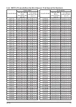
Page 33: ...201 HLP3500 09 04 HLP3500 10 04 HLP3202 HLP3500 09 05 HLP3500 10 05 HLP3203 HLP3500 09 05 HLP3500 10 05 HLP3204 HLP3500 09 05 HLP3500 10 05 Cassette Model Part Numbers Reaction Block Space Section 8 3...

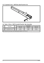
Page 34: ...ble of Parts HMT Extended Reaction Arm Assembly Item Description Qty Part Numbers HMT1500 HMT1500 HMT1500 1 Extended Reaction Arm 1 HTE15 HTE35 HTE75 2 Reaction Arm Pin 1 RAP15 RAP35 RAP75 Dispatched...

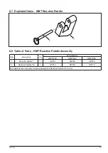
Page 35: ...ble of Parts HMT Reaction Paddle Assembly Item Description Qty Part Numbers HMT1500 HMT1500 HMT1500 1 Reaction Paddle 1 HRP15 HRP35 HRP75 2 Reaction Paddle Pin 1 RPP15 RPP35 RPP75 Dispatched as assemb...

Page 36: ...SQ3500DPK HSQ7500DPK Items marked supplied in Ratchet Kit HSQ1500RK HSQ3500RK HSQ7500RK Items marked dispatched alongside Reaction Arm HSQ1500 04 HSQ3500 04 HSQ7500 04 Items marked dispatched alongsid...

Page 37: ...lable 18 Rod End Pin Spring 2 19 Drive Pin Retainer 2 20 Reaction Arm Grub Screw 1 21 Drive Retainer Ring 1 22 Front Spacer Pin 2 Not available Not available Not available 23 Link Pin Assembly Lanyard...

Page 38: ...el Assembly Items marked supplied in Swivel Seal Kits Note Refer to the wrench instruction sheet for detailed maintenance instruction Apply silicone grease to O rings Apply Loctite 243 Thread Sealant...

Page 39: ...ws 4 5 Swivel Manifold Post 1 SP300101 6 O Ring 2 7 Adaptor 10 000 psi 8 Male Coupling 10 000 psi 9 Female Coupling 10 000 psi 10 Dust Cap for male coupler 1 11 Dust Cap for female coupler 1 Indicates...

Page 40: ...ol valve of the pump unit Disassemble the pump and clean the direction control valve Piston will not retract Hose connections reversed Check the advance on the pump is connected to the advance on the...

Page 41: ...________________ ____________________________________________________________________________________ ____________________________________________________________________________________ _____________...

Page 42: ...________________ ____________________________________________________________________________________ ____________________________________________________________________________________ _____________...

Page 43: ...________________ ____________________________________________________________________________________ ____________________________________________________________________________________ _____________...

Page 44: ...2020 Enerpac Tool Group All Rights Reserved www enerpac com...

Reviews: