Doc
L4540
_a
15
In this screen the user can enter the parameters of
the elements used in the EVOP movements, such as
the cylinder installed for the application, the stroke
sensors and the pressure transducers used to set the
calculations of the movement.
In the boxes the user can type the following data (refer
to Figure 20 for the position number):
1. Units button: The user can switch a different units
system pushing this button. The units can be
international for the International System of Units,
or Imperial for the Imperial System of Units.
2. Cylinder type: The user can select the type of
cylinder being used with the HPU (single/double
acting).
3. Position span: The user must type the maximum
range of the stroke sensor which monitors the
cylinder.
The standard stroke sensors position spans are 100,
125, 375, 500 ,750, 1000, 1250 and 2000 mm.
4. Cylinder stroke: The user must type the maximum
stroke of the cylinder.
5. A line pressure span: The user must type the
maximum range of the A line pressure transducer.
6. B line pressure span: The user must type the
maximum range of the B line pressure transducer.
Stardard pressure transducers have a maximum reading
of 11,600 psi (800 bar).
7. A line effective area: The user must type the surface
area of the pushing side of the cylinder conected
to A line.
8. B line effective area: The user must type the surface
area of the pulling side of the cylinder conected to
B line.
Information of sensors and cylinders is available either
on the product label or online at www.enerpac.com.
For single acting cylinders, B line parameters are
blocked and appear shaded.
Figure 21: Spans Screen Single Acting Cylinders
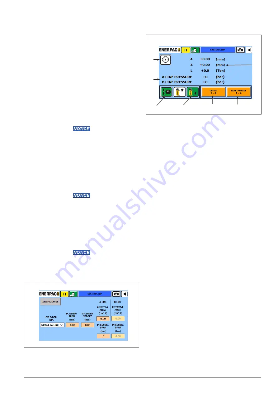
8.5 Offset Screen
Figure 22: Offset Screen Details
Offset is generally used to have a dimension reference
when a load is going to be lifted to an unknown
dimension and that load is subsequently lowered to
the same location. Since the wire of the stroke sensor
will normally need to be extended a short distance to
engage the bottom of the load, the offset screen can
save that value so the user can reference that starting
point after the lift is completed. By assigning an offset
value prior to start lifting the load, the user will have a
reference point where the lift started.
“A” value normally represents the absolute extension of
the stroke sensor between 0 and full extension. When
the user presses and holds the Offset button (A=0), the
current “A” value is stored in the memory as “Z”, and “A”
is reset to zero. “A” now becomes the reference value
for the starting point of the lift. When the lift is complete,
the user can press Reset button (Z=0) to reset “A” back
to normal value.
In this screen the following elements are shown:
1. Pressure button: Pushing in the pressure icon, the
operator can check the internal pressure of the
cylinder.
2. Pressure line: This section shows the pressure at
A line (big chamber) and B line (small chamber) of
the hydraulic circuit.
3. Manual button: Select this button to activate
the manual mode operation. When this button is
selected, the background color of the button will
become green. Use this button to make small
movements in the application. Refer to paragraph
“8.10 Manual Screen” and “9.4 Manual Mode” for
further details concerning the manual movements.
4. Upward/Downward buttons: When the manual
button is selected, the operator must select
the type of movement to be executed between
upward (the plunger moves out of the cylinder) and
downward (the plunger gets in the cylinder).
5. Offset button: Push and hold this button for 3
seconds to convert value A into 0 and Z will keep
the current value of A.
7
3
4
5
1
2
6


