

12
5. MAINTENANCE AND INSPECTION
5.1 Maintenance
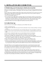
• Check the water supply device and the release often. You should avoid the condition of no water or air
entering into the system as this will influence the unit’s performance and reliability. You should clear the pool/
spa filter regularly to avoid damage to the unit as a result of a clogged filter.
• The area around the unit should be dry, clean and well ventilated. Clean the side heating exchanger regularly
to maintain good heat exchange and conserve energy.
• The operation pressure of the refrigerant system should only be serviced by a certified technician.
• Check the power supply and cable connection often. Should the unit begin to operate abnormally, switch it off
and contact your qualified technician.
• Discharge all water in the water pump and water system, so that freezing of the water-inlet the pump or water
system does not occur. You should discharge the water at the bottom of the water pump if the unit will not be
used for an extended period of time. You should check the unit thoroughly and fill the system with water fully
before using it for the first time after a prolonged period of no usage.
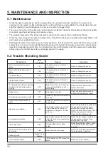
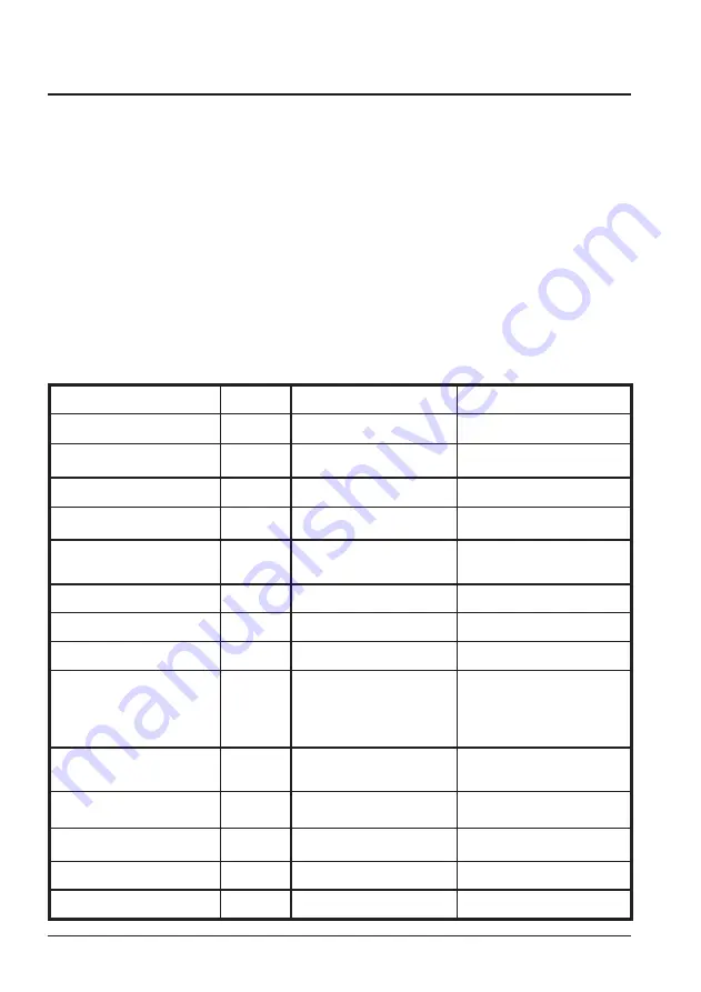
5.2 Trouble Shooting Guide
Malfunction
LED
Controller
Reason
Resolution
Water-inlet temperature sensor
failure
PP1
The sensor is open or there is a
short circuit
Check or change the sensor
Water-outlet temperature sensor
failure
PP2
The sensor is open or there is a
short circuit
Check or change the sensor
Coil sensor failure
PP3
The sensor is open or there is a
short circuit
Check or change the sensor
Ambient sensor failure
PP5
The sensor is open or there is a
short circuit
Check or change the sensor
The temperature difference between
the water-inlet and water-outlet is
too large
PP6
Water flow volume is not enough,
water pressure difference is too
low/too large
Check the water flow volume, or
system obstruction.
Defrost cycle
PP7
Outlet water is too low
Check the water flow volume or
outlet water temperature sensor
First level frost protection in winter
PP7
Ambient or inlet water temperature
is too low
Second level frost protection in
winter
PP7
Ambient or inlet water temperature
is even lower
High pressure protection
EE1
Gas System pressure is too high,
or water flow rate is too low, or
evaporator is clogged, or air flow
is too low
Check the high pressure switch and
the gas system pressure to see
whether the gas loop is blocked.
Check the water flow volume. Check
that the evaporator coil is clean.
Check the fan rotation speed
Low pressure protection
EE2
Gas System pressure is too low, or
air flow is too low or evaporator coil
is clogged
Check the low pressure switch and
the gas system pressure to see
whether there is a leak
Flow switch failure
EE3
No water/little water in water
system
Check the water flow volume, check
if the water pump and flow switch
has failed
PP6 alarm code occurred 3 times in
30 minutes
EE5
Water flow rate not enough
Check the water flow rate, check if
the water system is jammed
Defrosting cycle
Defrost Code
Display
Communication failure
EE8
LED controller or PCB connection
failure
Check the wire connection
Summary of Contents for ELE01101
Page 19: ...17 6 ANNEXE 6 4 Vue éclatée et pièces détachées ...
Page 22: ...SWIMMING POOL HEAT PUMP UNIT Installation Instruction Manual ENERGYLINE ...
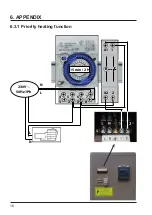
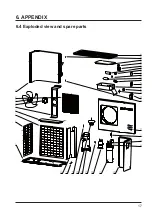
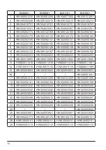
Page 40: ...17 6 APPENDIX 6 4 Exploded view and spare parts ...
Page 43: ...UNIDAD DE BOMBA DE CALOR PARA PISCINAS Manual de Instalación e Instrucciones ENERGYLINE ...
Page 61: ...17 6 APÉNDICE 6 4 Vista fragmentada y piezas sueltas ...
Page 64: ...BOMBA DE AQUECIMENTO PARA PISCINAS Manual de instalação e de instruções ENERGYLINE ...
Page 82: ...17 6 ANEXO 6 4 Perspectiva de explosão e peças de substituição ...
Page 85: ...HEIZPUMPENANLAGE FÜR EIN SCHWIMMBECKEN Einbau Anleitungshandbuch ENERGYLINE ...
Page 103: ...17 6 ANHANG 6 4 Explodierte Ansicht und Ersatzteile ...
Page 106: ...ZWEMBAD WARMTEPOMP Installatie en bedieningshandleiding ENERGYLINE ...
Page 124: ...17 6 AANHANGSEL 6 4 Opengewerkte tekening en wisselstukken ...
Page 145: ...17 6 APPENDICE 6 4 Esploso e parti di ricambio ...
Page 148: ...Varmepumpe til svømmebasseng Installerings og brukerveiledning ENERGYLINE ...
Page 166: ...17 6 Vedlegg 6 4 Sprengskisse og reservedeler ...
Page 169: ...ТЕПЛОВОЙ НАСОС ДЛЯ ПЛАВАТЕЛЬНОГО БАССЕЙНА Руководство по монтажу и эксплуатации ENERGYLINE ...
Page 187: ...17 6 ПРИЛОЖЕНИЕ 6 4 Вид в разрезе и запасные части ...
Page 190: ......


