
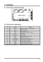
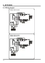
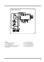


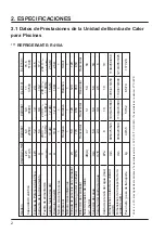


10
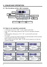
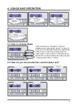
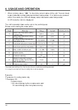
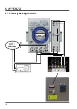
4. USAGE AND OPERATION
• When running, press “
◀ ▶
” to check the current status of the unit. You can check
water-inlet/water-outlet/condenser/ambient temperature. If no buttons are pressed
within 5 seconds, the LED will display water-inlet/water-outlet temperature.
In Off mode the clock is displayed.
The unit’s operation data can be set on the control panel.
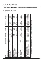
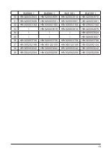
Please set according the below table:
The parameters setting (2-3-4-5-6) must be done by a professional (Refrigerationist).
In no way, the end user will have to modify the pre set parameters
Remarks:
*Parameter 0: cooling mode only.
**Parameter 09:
0: always open.
1: 60 second delay before compressors start.
30 second delay after compressors stop.
Digit
Meaning
Range
Default
Adjust (yes/no)
*0
Return water temperature setting
(cooling mode)
8-28°C
27°C
yes
1
Return water temperature setting
(heating mode)
15-40°C
27°C
yes
2
Total working time of compressor
after defrost cycle
30-90 MIN
45 MIN
no
3
Set defrost cycle start-up temperature
-30°C to 0°C
-6°C
no
4
Set defrost cycle stop temperature
0-30°C
13°C
no
5
Max. duration of defrost cycle
1-12 MIN
8 MIN
no
6
System quantity
1-2
2
no
7
Automatic restarting
0-1
0 (no) 1 (yes)
1
yes
8
Modes (cooling only/ Cooling &
Heating /auxiliary electrical heating
N/A / Heating Only)
0/1/2/3
3
yes
**9
Filtration pump contact
0/1
1
yes
Summary of Contents for ELE01101
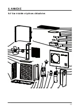
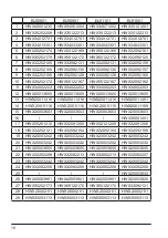
Page 19: ...17 6 ANNEXE 6 4 Vue éclatée et pièces détachées ...
Page 22: ...SWIMMING POOL HEAT PUMP UNIT Installation Instruction Manual ENERGYLINE ...
Page 40: ...17 6 APPENDIX 6 4 Exploded view and spare parts ...
Page 43: ...UNIDAD DE BOMBA DE CALOR PARA PISCINAS Manual de Instalación e Instrucciones ENERGYLINE ...
Page 61: ...17 6 APÉNDICE 6 4 Vista fragmentada y piezas sueltas ...
Page 64: ...BOMBA DE AQUECIMENTO PARA PISCINAS Manual de instalação e de instruções ENERGYLINE ...
Page 82: ...17 6 ANEXO 6 4 Perspectiva de explosão e peças de substituição ...
Page 85: ...HEIZPUMPENANLAGE FÜR EIN SCHWIMMBECKEN Einbau Anleitungshandbuch ENERGYLINE ...
Page 103: ...17 6 ANHANG 6 4 Explodierte Ansicht und Ersatzteile ...
Page 106: ...ZWEMBAD WARMTEPOMP Installatie en bedieningshandleiding ENERGYLINE ...
Page 124: ...17 6 AANHANGSEL 6 4 Opengewerkte tekening en wisselstukken ...
Page 145: ...17 6 APPENDICE 6 4 Esploso e parti di ricambio ...
Page 148: ...Varmepumpe til svømmebasseng Installerings og brukerveiledning ENERGYLINE ...
Page 166: ...17 6 Vedlegg 6 4 Sprengskisse og reservedeler ...
Page 169: ...ТЕПЛОВОЙ НАСОС ДЛЯ ПЛАВАТЕЛЬНОГО БАССЕЙНА Руководство по монтажу и эксплуатации ENERGYLINE ...
Page 187: ...17 6 ПРИЛОЖЕНИЕ 6 4 Вид в разрезе и запасные части ...
Page 190: ......


