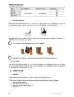
ASSEMBLY AND USER MANUAL
Combi [6 | 12 | 16] & Combi 12 HT
8
www.energie.pt
4.3.
Components
4.3.1.
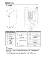
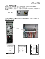
Combi Block
IMPORTANT
* The Combi Block has one 10 l expansion vessel sized for heating line with
≤ 120 l
(7 bar safety valve and
pre-charge circuit of 1,5bar). If the heating installation has more than 120 l, a new expansion vessel
should be sized.
**
It’s mandatory to install the filter
(supplied with the system) on the heating line.
***
It’s
mandatory to install the safety valve (supplied with the system) on the heating line.
Symbol
Meaning
[A]
Aspiration Line
[B]
Liquid Line
[C]
DHW Outlet
[D]
DHW Inlet
[E]
Heating Inlet
[F]
Heating Outlet
[G]
Tank electric
heater
[H]
Coil Outlet
[I]
Coil Inlet
[J]
Mg anode
Compressor
Symbol
Meaning
Thermostatic
expansion valve
Dry filter
Liquid receiver
Plate heat exchanger
Drain valve
Circulator pump
Symbol
Meaning
Flow switch
Expansion vessel 5 l
Expansion vessel 10 l*
Cut-off valve
Air vent
Three way valve
Safety valve ***
Line electric heater
“y” filter**
G
D
C
G
Cut of upper
view from tank
J
H
S4
J
I


