ASSEMBLY AND USER MANUAL
Combi [6 | 12 | 16] & Combi 12 HT
www.energie.pt
15
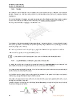
If a shaft is too long for the length required, it must be rolled up and never cut.
If it is wished to shorten or elongate, this operation must be carried out on all the shafts with the same diameter.
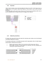
All ø ¼” s
hafts must be welded to the lower connections of the panels (liquid inlet). The shafts of the main distributor
must be welded to the secondary distributors.
✓
A
–
Main Liquid Line
✓
B
–
Main Liquid Line viewed from above.
It is vital that the power shafts (Ø
1/4’’) should have the same length and the same is true of the main
distributor shafts.
Depending on the Thermodynamic Block model and the position of the panels, one or more aspiration collectors
must be carried out.
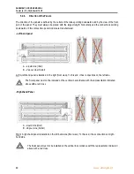
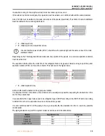
The aspiration which allows the collection of the refrigerant fluid in its gaseous state must regroup all the panel
aspiration outlets (
∅
3/8’’) as far as the collector.
This is shown in the figure below.
✓
B
–
Main Aspiration Line.
All the shafts must be welded to the upper panel outlets.
It is important for the connections at the collectors to be as simple as possible, respecting the instructions in the
event of any unevenness.
It is essential for the copper tubes used to be refrigerant type CUDHP according to the ISO1337 and/or according
to EN12735, both on the aspiration line and on the liquid line (power).
It is also recommended for all the piping to have good quality thermal insulation in order to avoid any possible
condensation.
The piping diameters vary with the system model as can be seen in the table below.
Model
Aspiration Line
Liquid Line
Combi 6
3/4’’
1/2’’
Combi 12
7/8’’
1/2’’
Combi 16
7/8’’
3/4’’
Combi 12 HT
7/8’’
1/2’’


