background image

Operation

Proline Promag 55 FOUNDATION Fieldbus

54

Hauser

5.2.2

Display (operating mode)

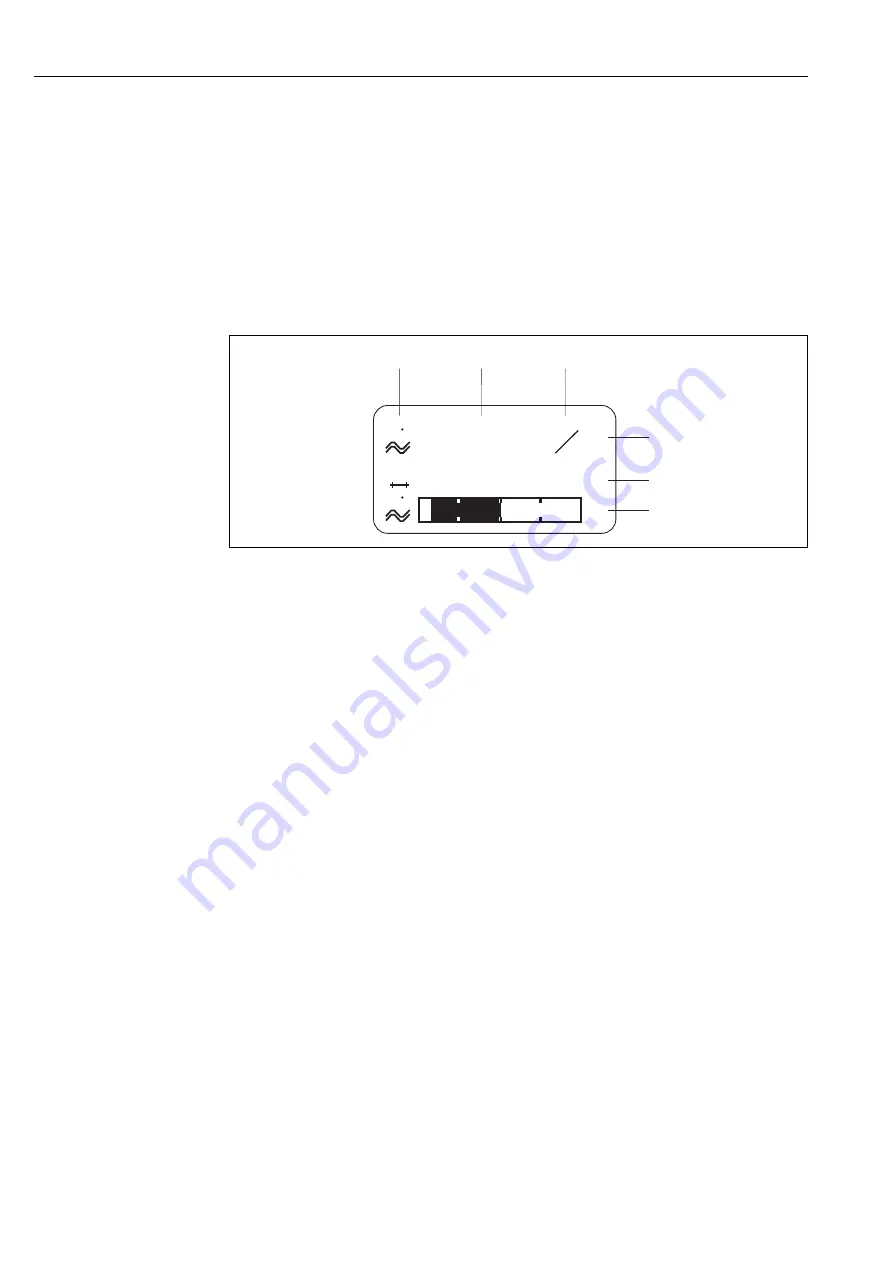
The display area consists of three lines in all; this is where measured values are displayed, and/or 
status variables (direction of flow, bar graph, etc.). You can change the assignment of display lines 
to variables at will in order to customize the display to suit your needs and preferences (

see the 

"Description of Device Functions" manual).

Multiplex mode:

A maximum of two different display variables can be assigned to each line. Variables multiplexed in 
this way alternate every 10 seconds on the display.

Error messages:

Display and presentation of system/process errors 

ä

58

a0001173

Fig. 41: 

Typical display for normal operating mode (HOME position)

1

Main line shows main measured values, e.g. flow

2

Supplementary line shows supplementary measured or status variables, e.g. totalizer reading.

3

Information line shows additional information on measured or status variables,
e.g. bar graph representation of the full scale value attained by the flow rate

4

"Info icons" field shows additional information in the form of icons on the measured values displayed. A complete 
overview of all icons and their meaning can be found on 

ä

55

5

"Measured values" field shows the current measured values

6

"Engineering unit" field shows the engineering units and time units defined for the current measured values.

!

Note! 
In the HOME position, you can use the 

OS 

keys to call up a list containing the following 

information:
• Totalizer values (including overflow)
• Tag name (DEVICE PD-TAG)

OS 

key 

→ 

queries individual values in the list

Simultaneously press Esc key (

X

→ 

Return to the HOME position

1

4

5

6

2

3

+24.502

+1863.97

x

x

y

y

–50

+50

%

v

v

3

S

Summary of Contents for Proline Promag 55

Page 1: ...BA126D 06 EN 07 09 71089883 Valid as of version V 3 00 XX device software Operating Instructions Proline Promag 55 FOUNDATION Fieldbus Electromagnetic Flow Measuring System ...

Page 2: ......

Page 3: ...emote version 39 4 3 1 Connecting the sensor 39 4 3 2 Cable specifications 43 4 4 Connecting the measuring unit 44 4 4 1 Connecting the transmitter 44 4 4 2 Fieldbus connector 46 4 4 3 Terminal assignment 47 4 5 Potential equalization 48 4 5 1 Potential equalization Promag S 48 4 5 2 Potential equalization Promag H 48 4 5 3 Connection examples for potential equalization 48 4 6 Degree of protection...

Page 4: ...stalling electronics boards 93 9 4 2 Replacing the device fuse 97 9 5 Return 98 9 6 Disposal 98 9 7 Software history 98 10 Technical data 99 10 1 Technical data at a glance 99 10 1 1 Application 99 10 1 2 Function and system design 99 10 1 3 Input 99 10 1 4 Output 100 10 1 5 Power supply 102 10 1 6 Performance characteristics 103 10 1 7 Operating conditions Installation 104 10 1 8 Operating condit...

Page 5: ...temperature concentration or the degree of contamination in the process can result in changes to the chemical resistance properties For this reason Endress Hauser does not accept any responsibility with regard to the corrosion resistance of materials wetted by fluids in a specific application The user is responsible for the choice of wetted materials with regard to their in process resistance to c...

Page 6: ...ave penetrated crevices or diffused through plastic Costs incurred for waste disposal and injury burns etc due to inadequate cleaning will be charged to the owner operator 1 5 Notes on safety conventions and icons The devices are designed and tested to meet state of the art safety requirements and have left the factory in a condition in which they are safe to operate The devices comply with the ap...

Page 7: ...Power supply frequency power consumption 3 Additional functions and software EPD with empty pipe detection electrode 4 FOUNDATION Fieldbus equipped with FOUNDATION Fieldbus H1 interface ITK 5 01 certified by the Fieldbus Foundation Interoperability Test Kit revision 5 01 DEVICE ID FOUNDATION Fieldbus device identification 5 Reserved for additional information on special products 6 Observe device d...

Page 8: ...for additional information on special products 7 Permitted ambient temperature range 8 Please comply with the Operating Instructions 9 Reserved for additional information on device version approvals certificates 10 Calibration tolerance 11 Additional information EPD with empty pipe detection electrode R B with reference electrode 12 Degree of protection 13 Flow direction 20 C 4 F Tamb 50 C 122 F N...

Page 9: ...ice software currently installed incl language group 7 Type of communication installed 8 Information on current communication software Device Revision Device Description 9 Date of installation 10 Current updates to data specified in points 6 to 9 26 27 NC Versorgung Tension d alimentation Observer manuel d instruction See operating manual Betriebsanleitung beachten Communication Drivers Device SW ...

Page 10: ...s of the Australian Communications and Media Authority ACMA 2 3 FOUNDATION Fieldbus device certification The flowmeter has passed all the test procedures implemented and has been certified and registered by the Fieldbus Foundation The device thus meets all the requirements of the following specifications Certified to FOUNDATION Fieldbus specification The flowmeter meets all the specifications of t...

Page 11: ...rs with PTFE linings Special notes on flanged devices Caution The wooden covers mounted on the flanges before the device leaves the factory protect the linings on the flanges during storage and transportation Do not remove these protection plates until immediately before the device is installed in the pipe Do not lift flanged devices by the transmitter housing or in the case of the remote version ...

Page 12: ...ect it reliably against impact for storage and transportation The original packaging provides optimum protection The storage temperature corresponds to the operating temperature range of the measuring transmitter and the appropriate measuring sensors ä 104 The measuring device must be protected against direct sunlight during storage in order to avoid unacceptably high surface temperatures Choose a...

Page 13: ...int of a pipeline Risk of air accumulating Directly upstream from a free pipe outlet in a vertical pipeline A0011899 Fig 6 Mounting location Installing pumps Do not install the sensor on the intake side of a pump This precaution is to avoid low pressure and the consequent risk of damage to the lining of the measuring tube Information on the lining s resistance to partial vacuum ä 107 It might be n...

Page 14: ...n It is advisable to install a cleaning valve A0011901 Fig 8 Installation in partially filled pipe Down pipes Install a siphon or a vent valve downstream of the sensor in down pipes longer than 5 meters 16 ft This precaution is to avoid low pressure and the consequent risk of damage to the lining of the measuring tube This measure also prevents the system losing prime which could cause air inclusi...

Page 15: ...en using empty pipe detection For sludge containing sand or stones and where the solids cause sedimentation A0011903 Fig 10 Vertical orientation Horizontal orientation The measuring electrode plane should be horizontal This prevents brief insulation of the two electrodes by entrained air bubbles Caution Empty Pipe Detection functions correctly with the measuring device installed horizontally only ...

Page 16: ...cessary in order to ensure measuring accuracy Inlet run 5 DN Outlet run 2 DN A0011905 Fig 12 Inlet and outlet runs 3 2 5 Vibrations Secure and fix both the piping and the sensor if the vibrations are severe Caution It is advisable to install sensor and transmitter separately if vibration is excessively severe Information on the permitted resistance to vibration and shock ä 104 A0011906 Fig 13 Meas...

Page 17: ...ouble flange reducers can be used to install the sensor in larger diameter pipes The resultant increase in the rate of flow improves measuring accuracy with very slow moving fluids The nomogram shown here can be used to calculate the pressure loss caused by cross section reduction Note The nomogram only applies to liquids of viscosity similar to water 1 Calculate the ratio of the diameters d D 2 F...

Page 18: ...ity can be increased if necessary by reducing the nominal diameter of the sensor through the use of adapters ä 17 Flow characteristic values for Promag S sensor SI units Nominal diameter Recommended flow rate Factory settings mm Min max full scale value v 0 3 or 10 m s Low flow cut off v 0 04 m s 15 4 to 100 dm3 min 0 5 dm3 min 25 9 to 300 dm3 min 1 dm3 min 32 15 to 500 dm3 min 2 dm3 min 40 25 to ...

Page 19: ...0 gal min 0 50 gal min 1 7 to 190 gal min 0 75 gal min 2 10 to 300 gal min 1 25 gal min 2 16 to 500 gal min 2 0 gal min 3 24 to 800 gal min 2 5 gal min 4 40 to 1250 gal min 4 0 gal min 5 60 to 1950 gal min 7 0 gal min 6 90 to 2650 gal min 12 gal min 8 155 to 4850 gal min 15 gal min 10 250 to 7500 gal min 30 gal min 12 350 to 10600 gal min 45 gal min 14 500 to 15000 gal min 60 gal min 16 600 to 190...

Page 20: ...dm3 5 dm3 min 65 2 1 2 60 to 2000 dm3 min 500 dm3 min 5 00 dm3 8 dm3 min 80 3 90 to 3000 dm3 min 750 dm3 min 5 00 dm3 12 dm3 min 100 4 145 to 4700 dm3 min 1200 dm3 min 10 00 dm3 20 dm3 min Nominal diameter Recommended flow rate Factory settings inch mm Min max full scale value v 0 3 or 10 m s Full scale value v 2 5 m s Pulse value 2 pulse s Low flow cut off v 0 04 m s 1 12 2 0 015 to 0 5 gal min 0...

Page 21: ...otential equalization between sensor and transmitter if necessary The permissible cable length Lmax depends on the fluid conductivity å 16 å 17 Promag S a0006116 Fig 16 Permitted lengths for connecting cable in remote version as a function of the conductivity of the fluid Gray shaded area permissible range Lmax length of connecting cable Promag H A0010734 Fig 17 Permitted lengths for connecting ca...

Page 22: ... ä 23 If grounding disks are used follow the mounting instructions which will be enclosed with the shipment A0011908 Fig 18 Sensor installation Seals Comply with the following instructions when installing seals Hard rubber lining Additional seals are always required Natural rubber lining Seals may not be used PFA PTFE or PU polyurethane lining No seals are required Make sure that the seals do not ...

Page 23: ...5 PN 40 8 M 16 27 43 40 32 80 PN 16 8 M 16 13 34 53 48 40 80 PN 40 8 M 16 34 53 48 40 100 PN 16 8 M 16 14 36 57 51 43 100 PN 40 8 M 20 50 78 70 59 125 PN 16 8 M 16 19 48 75 67 56 125 PN 40 8 M 24 71 111 99 83 150 PN 16 8 M 20 27 63 99 85 74 150 PN 40 8 M 24 88 136 120 104 200 PN 10 8 M 20 35 91 141 101 106 200 PN 16 12 M 20 28 61 94 67 70 200 PN 25 12 M 24 92 138 105 104 250 PN 10 12 M 20 27 71 11...

Page 24: ... 7 4 18 15 1 Class 300 4 11 25 23 2 Class 150 4 5 8 16 35 32 2 Class 300 8 5 8 8 1 17 16 3 Class 150 4 5 8 15 32 58 49 44 3 Class 300 8 19 35 31 28 4 Class 150 8 5 8 11 23 41 37 31 4 Class 300 8 30 49 44 43 6 Class 150 8 24 44 78 63 58 6 Class 300 12 38 54 49 52 8 Class 150 8 38 59 105 80 79 10 Class 150 12 7 8 42 55 100 75 12 Class 150 12 7 8 58 76 131 98 14 Class 150 12 1 77 117 192 100 16 Class...

Page 25: ...4 41 37 40 20K 4 M 16 24 41 37 50 10K 4 M 16 33 54 46 50 20K 8 M 16 17 27 23 65 10K 4 M 16 18 45 74 63 55 65 20K 8 M 16 23 37 31 28 80 10K 8 M 16 10 23 38 32 29 80 20K 8 M 20 35 57 46 42 100 10K 8 M 16 12 29 47 38 35 100 20K 8 M 20 48 75 58 56 125 10K 8 M 20 20 51 80 66 60 125 20K 8 M 22 79 121 103 91 150 10K 8 M 20 25 63 99 81 75 150 20K 12 M 22 72 108 72 81 200 10K 12 M 20 23 52 82 54 61 200 20K...

Page 26: ...able E 12 M 20 37 300 Table E 12 M 24 57 350 Table E 12 M 24 85 400 Table E 12 M 24 99 450 Table E 16 M 24 96 500 Table E 16 M 24 115 600 Table E 16 M 30 199 Sensor Nominal diameter AS 4087 Pressure rating Screws Max tightening torque Nm mm PTFE Natural rubber 50 PN 16 4 M 16 42 80 PN 16 4 M 16 16 100 PN 16 4 M 16 13 150 PN 16 8 M 16 20 200 PN 16 8 M 16 33 250 PN 16 8 M 20 64 300 PN 16 12 M 20 55 ...

Page 27: ... exceeds 150 C 300 F Note You will find information on permissible temperature ranges on ä 105 Insulation Pipes generally have to be insulated if they carry very hot fluids to avoid energy losses and prevent accidental contact with pipes at temperatures that could cause injury Guidelines regulating the insulation of pipes have to be taken into account Caution Risk of electronics overheating The ho...

Page 28: ...rocess connections with aseptic gasket seals Weld nipples DIN 11850 ODT SMS Clamp ISO 2852 DIN 32676 L14 AM7 coupling DIN 11851 DIN 11864 1 SMS 1145 flange DIN 11864 2 C DN 40 to 100 1 to 4 process connections with aseptic gasket seals Weld nipples DIN 11850 ODT SMS Clamp ISO 2852 DIN 32676 L14 AM7 coupling DIN 11851 DIN 11864 1 ISO 2853 SMS 1145 flange DIN 11864 2 Seals When installing the proces...

Page 29: ... rings can be ordered separately from Endress Hauser as accessories ä 79 When placing the order make certain that the ground ring is compatible with the material used for the electrodes Otherwise there is a risk that the electrodes may be destroyed by galvanic corrosion Information about the materials can be found on ä 111 Ground rings including the seals are mounted within the process connections...

Page 30: ... seal from the pipe 2 Weld the process connection to the pipe 3 Reinstall the sensor in the pipe Make sure that everything is clean and that the seal is correctly seated Note If thin walled foodstuffs pipes are not welded correctly the heat could damage the installed seal It is therefore advisable to remove the sensor and the seal prior to welding The pipe has to be spread approximately 8 mm to pe...

Page 31: ... as far as it will go 4 Turn the transmitter housing to the desired position max 2 90 in either direction 5 Lower the housing into position and reengage the bayonet catch 6 Retighten the two securing screws a0004302 Fig 22 Turning the transmitter housing aluminum field housing Turning the stainless steel field housing 1 Loosen the two securing screws 2 Carefully lift the transmitter housing as far...

Page 32: ...the latches on the side of the display module and pull the module out of the electronics compartment cover 3 Turn the display to the desired position max 4 45 in both directions and position it back on the electronics compartment cover 4 Screw the cover of the electronics compartment firmly onto the transmitter housing a0003236 Fig 24 Turning the local display field housing 4 x 45 ...

Page 33: ...vice in a shady location Avoid direct sunlight Always install the wall mount housing in such a way that the cable entries are pointing down Mounted directly on the wall 1 Drill the holes as illustrated 2 Remove the cover of the connection compartment a 3 Push the two securing screws b through the appropriate bores c in the housing Securing screws M6 max Ø 6 5 mm 0 24 Screw head max Ø 10 5 mm 0 4 4...

Page 34: ...the panel wall Afterwards tighten the locking nuts Additional support is not necessary a0001131 Fig 26 Panel mounting wall mount housing Pipe mounting The assembly should be performed by following the instructions in the following diagram Caution If the device is mounted to a warm pipe make sure that the housing temperature does not exceed 60 C 140 F which is the maximum permissible temperature a0...

Page 35: ...rection of flow through the pipe Is the position of the measuring electrode plane correct ä 15 Is the position of the empty pipe detection electrode correct ä 15 Were all screws tightened to the specified torques when the sensor was installed Chap 3 3 Were the correct seals installed type material installation ä 22 Are the measuring point number and labeling correct visual inspection Process envir...

Page 36: ... A or B are particularly preferable for new installations Only these types have cable shielding that guarantees adequate protection from electromagnetic interference and thus the most reliable data transfer With cable type B more than one fieldbus with the same degree of protection may be operated in a cable No other circuits are permissible in the same cable Practical experience has shown that ca...

Page 37: ...protection bus power option current consumption of field device A maximum of four field devices can be connected to a spur 4 1 5 Shielding and grounding The optimum electromagnetic compatibility of the fieldbus system is guaranteed only when system components and in particular lines are shielded and the shielding provides the most complete coverage possible Shield coverage of 90 is ideal Shielding...

Page 38: ...magnetic compatibility of systems it is important that the system components and above all the cables which connect the components are shielded and that no portion of the system is unshielded Ideally the cable shields are connected to the normally metal housings of the connected field devices Since these are generally connected to the protective earth the shield of the bus cable is grounded many t...

Page 39: ...cover from the connection compartment a 2 Sensor Remove the cover from the connection housing b 3 Feed the signal cable c and coil current cable d through the appropriate cable entries Caution Secure the connecting cable see Length of connecting cable ä 104 4 Terminate the signal and coil current cable in accordance with the table Promag S Please see the Cable termination table ä 41 Promag S Pleas...

Page 40: ... 6 brown 7 8 white 4 green 37 36 yellow A0011747 Fig 29 Connecting the remote version of the Promag H a Connection compartment wall mount housing b Connection housing sensor c Signal cable d Coil current cable n c Not connected insulated cable shields n c Cable colors numbers for terminals 5 6 brown 7 8 white 4 green 37 36 yellow E1 E2 GND E S1 E1 E2 S2 GND E S 5 7 4 37 42 41 42 41 6 5 7 8 4 37 36...

Page 41: ...cable Coil current cable Insulate one core of the three core wire at the level of the core reinforcement you only require two cores for the connection TRANSMITTER Signal cable Coil current cable A0002687 ae A0002688 ae SENSOR Signal cable Coil current cable A0002646 ae A0002650 ae m Cable end sleeve red Ø 1 0 mm 0 04 in n Cable end sleeve white Ø 0 5 mm 0 02 in Stripping for armored cables only A ...

Page 42: ...1 mm exception GND green cable Coil current cable Insulate one core of the three core wire at the level of the core reinforcement you only require two cores for the connection On the sensor side reverse both cable shields approx 15 mm over the outer jacket The strain relief ensures an electrical connection with the connection housing TRANSMITTER Signal cable Coil current cable A0002686 ae A0002684...

Page 43: ...o 176 F Cable permanently routed 40 to 80 C 40 to 176 F Cable cross section max 2 5 mm2 14 AWG a0003194 Fig 30 Cable cross section a Signal cable b Coil current cable 1 Core 2 Core insulation 3 Core shield 4 Core jacket 5 Core reinforcement 6 Cable shield 7 Outer jacket As an option Endress Hauser can also deliver reinforced connecting cables with an additional reinforcing metal braid We recommend...

Page 44: ...he connection compartment cover a from the transmitter housing 2 Feed the power supply cable b and fieldbus cable d through the appropriate cable entries Note The device can also be supplied with the option of a ready mounted fieldbus connector More information on this can be found on ä 46 3 Perform wiring in accordance with the respective terminal assignment and the associated wiring diagram Caut...

Page 45: ...und d Fieldbus cable Terminal no 26 FF with reverse polarity protection Terminal no 27 FF with reverse polarity protection e Fieldbus cable shield ground terminal Observe the following The shielding and grounding of the fieldbus cable ä 38 Ensure the stripped and twisted lengths of cable shield to the ground terminal are as short as possible f Service connector for connecting the service interface...

Page 46: ...ed instantly e g when constructing new star distributors using 4 channel or 8 channel distribution modules The device can therefore be supplied with the option of a ready mounted fieldbus connector Fieldbus connectors for retrofitting can be ordered from Endress Hauser as a spare part ä 79 a0006390 Fig 32 Connector for connecting to the FOUNDATION Fieldbus A Wall mount housing B Aluminum field hou...

Page 47: ...47 4 4 3 Terminal assignment Note The electrical characteristic quantities are listed in the Technical data section Terminal No inputs outputs Order version 20 21 22 23 24 25 26 FF 1 27 FF 1 55 K FOUNDATION Fieldbus 1 With integrated reverse polarity protection ...

Page 48: ... per the instructions for special cases ä 48 These special measures are particularly important when standard grounding measures cannot be applied or extreme equalizing currents are expected Sensors with brush electrodes do not have a reference electrode For this reason ground disks need to be installed in some cases to ensure sufficient potential equalization to the fluid This applies in particula...

Page 49: ...cessory from Endress Hauser A0011893 Fig 34 Via the transmitter s ground terminal and the pipe flanges Version with pre installed ground cable for DN 300 12 order option Ground cables copper wire min 6 mm 0 0093 in2 which are pre installed on the sensor flange are also optionally available These ground cables can be secured and connected electrically to the piping in different ways Using a screw o...

Page 50: ...8 Installation instructions cable entries Caution Do not loosen the screws of the sensor housing as otherwise the degree of protection guaranteed by Endress Hauser no longer applies Note The sensor Promag S can also be supplied with IP 68 rating permanent immersion in water to a depth of 3 meters In this case the transmitter must be installed remote from the sensor When using the measuring device ...

Page 51: ...partment Are all screw terminals firmly tightened Have the measures for grounding potential equalization been correctly implemented ä 48 Are all cable entries installed firmly tightened and correctly sealed Cables looped as water traps ä 50 Are all housing covers installed and firmly tightened Electrical connection of FOUNDATION Fieldbus H1 Notes Are all the connecting components T boxes junction ...

Page 52: ...e available to users for this purpose 3 Jumpers for diverse hardware settings ä 61 Jumpers on the I O board provide the means of setting the following hardware parameters for the FOUNDATION Fieldbus Enabling disabling the simulation mode in the function blocks e g AI DO function block Switching the hardware write protection on and off a0006391 Fig 39 FOUNDATION Fieldbus operating options 1 Local d...

Page 53: ... line liquid crystal display shows measured values dialog texts fault messages and notice messages The display as it appears when normal measuring is in progress is known as the HOME position operating mode Display 2 Optical sensors for Touch Control 3 O S keys HOME position Direct access to totalizer values and actual values of inputs outputs Enter numerical values select parameters Select differ...

Page 54: ...e shows main measured values e g flow 2 Supplementary line shows supplementary measured or status variables e g totalizer reading 3 Information line shows additional information on measured or status variables e g bar graph representation of the full scale value attained by the flow rate 4 Info icons field shows additional information in the form of icons on the measured values displayed A complet...

Page 55: ...d below is output depending on the assignment of the lines in the local display OUT value manipulated variable IN value control variable CAS_IN value external set point The messages listed below describe the status of the OUT value of the Analog Input function block and the value assigned to the PID function block OK Status GOOD valid UNC Status UNCERTAIN conditionally valid BAD Status BAD invalid...

Page 56: ... group e g SYSTEM UNITS F 4 O S Select a function group e g CONFIGURATION F 5 Select a function e g UNIT VOLUME FLOW and change parameters enter numerical values OS Select or enter release code parameters numerical values F Save entries 6 Exit the function matrix Press and hold down Esc key X for longer than 3 seconds HOME position Repeatedly press Esc key X Return step by step to HOME position a0...

Page 57: ...ured values are output via the signal outputs in the normal way If the power supply fails all preset and parameterized values remain safely stored in the EEPROM 5 3 2 Enabling the programming mode The function matrix can be disabled Disabling the function matrix rules out the possibility of inadvertent changes to device functions numerical values or factory settings A numerical code factory settin...

Page 58: ...4 2 Error message type The device always assigns system and process errors to two error message types fault or notice message with the result that they are evaluated differently ä 81 Critical system errors e g module defects are always identified and displayed as fault messages by the measuring device Notice message The error in question has no effect on the current operation Displayed as exclamat...

Page 59: ...of device specific parameters General information on FOUNDATION Fieldbus is provided in the Operating Instructions FOUNDATION Fieldbus Overview BA013S available at www endress com Download System files You will need the following files for commissioning and network configuration Commissioning Device description Device Description sym ffo Network configuration CFF file Common File Format cff You ca...

Page 60: ...on DD and Capability File CFF www endress com Download Software Driver CD ROM Endress Hauser order number 56003896 www fieldbus org Device driver for the FF host systems Sources for obtaining ABB FieldController 800 www abb com Allen Bradley Control Logix See FF standard device driver Emerson Delta V www easydeltav com Endress Hauser ControlCare See FF standard device driver Honeywell Experion PKS...

Page 61: ...d is the reverse of the removal procedure A0004731 Fig 44 Hardware configuration I O board 1 Jumper for switching on off the write protection 1 1 Write protection switched off default value write access to device functions via FF interface is possible 1 2 Write protection switched on default value write access to device functions via FF interface is not possible 2 Jumper for simulation mode 2 1 Si...

Page 62: ...rational The measuring device performs a number of post switch on self tests As this procedure progresses the following sequence of messages appears on the local display Normal measuring mode commences as soon as startup completes Various measured value and or status variables appear on the display HOME position Note If startup fails an error message indicating the cause is displayed PROMAG 55 STA...

Page 63: ...nected Promag 55 reports as follows E H_PROMAG_55_ xxxxxxxxxxx tag name PD TAG 452B481042 xxxxxxxxxxx Device_ID Block structure Display text xxx serial number Base index Description RESOURCE_xxxxxxxxxxx 400 Resource Block TRANSDUCER_FLOW_xxxxxxxxxxx 1400 Flow Transducer Block TRANSDUCER_DIAG_xxxxxxxxxxx 1600 Diagnosis Transducer Block TRANSDUCER_DISP_xxxxxxxxxxx 1800 Display Transducer Block TRANS...

Page 64: ... ordered by device specific functions The following description provides an example for the Flow Transducer Block base index 1400 10 Enter the desired block name optional Factory setting TRANSDUCER_FLOW_xxxxxxxxxxx 11 Open the Flow Transducer Block 12 Now configure the device specific parameters relevant for your application Note Changes to the device parameters can only be made after entering a v...

Page 65: ... g measurement range of the flow application for the process variable in question see the example below Caution Make sure that the selected unit is suitable for the measurement variable of the selected process variable Otherwise the BLOCK_ERROR parameter will display the error message Block Configuration Error and the block operating mode cannot be set to AUTO Process variable Channel parameter Ca...

Page 66: ...rning LO_LIM Limit value for the lower warning LO_LO_LIM Limit value for the lower alarm The limit values entered must be within the value range specified in the OUT_SCALE parameter group 21 In addition to the actual limit values you must also specify the action taken if a limit value is exceeded using so called alarm priorities parameters HI_HI_PRI HI_PRI LO_PR LO_LO_PRI See the Description of De...

Page 67: ...RGET parameter to OOS i e block Out Of Service 28 Using the CHANNEL parameter select Density which is to be used as the input value for the Transducer Block algorithm scaling function The following settings are possible 29 In the PV_SCALE parameter group select the desired engineering unit and the block input range measuring range of the density application for the relevant process variable see th...

Page 68: ...ers that are important for standard measuring operation can be configured easily and quickly using the Commissioning Quick Setup menu In the case of measuring devices without a local display the individual parameters and functions must be configured via the configuration program e g NI FBUS Configurator a0006395 en Fig 45 Quick Setup for straightforward commissioning n o Esc E XXX XXX XX 3001 3001...

Page 69: ...ption sets each selected unit to the factory setting The ACT SETTING option accepts the units previously set by you n Only units not yet configured in the current setup are offered for selection in each cycle The unit for Mass and Volume is derived from the corresponding flow unit o The YES option remains visible until all the units have been configured NO is the only option displayed when no furt...

Page 70: ...suring points Note For information on installing and removing the T DAT ä 92 a0001221 en Fig 46 Data backup transmission with T DAT SAVE LOAD function Information on the LOAD and SAVE options available LOAD Data are transferred from the T DAT to the EEPROM Note Any settings already saved on the EEPROM are deleted This option is only available if the T DAT contains valid data This option can be per...

Page 71: ... following preconditions must be met Solids content flow software option F CHIP Analog Output function block AO A density measuring device e g Gammapilot M from Endress Hauser for recording total fluid density i e incl solids Knowledge of the density of the solids e g resulting from laboratory testing Knowledge of the density of the transport fluid e g resulting from laboratory testing or from ref...

Page 72: ...lues to the solids content flow see the following examples Case study 1 You would like to configure the totalizer for totaling the overall mass flow rate of solids e g in tons 1 Open the ASSIGN function for the totalizer TOTALIZER CONFIGURATION ASSIGN 2 Assign the TARGET MASS FLOW variable to the totalizer Case study 2 You would like to issue a warning via the relay in case the solids content flow...

Page 73: ...reference values in the measuring system is always performed using the REFERENCE STATUS USER 7501 device function Caution An analysis of trends in diagnostic parameters without reference values is not possible Reference values should always be determined directly after commissioning This ensures that the saved reference values are values in the original status of the measuring system i e which hav...

Page 74: ... and VOLUME FLOW As the buildup typically develops over a period of months it is useful to present and evaluate the relevant measured data and parameters using suitable software for example using the Endress Hauser software package FieldCare with the Flow Communication FXA193 291 DTM and Fieldsafe Module Function group diagnostic parameters Possible causes of deviations from the reference value CO...

Page 75: ...or can be output by means of the configurable relay outputs Performing empty pipe and full pipe adjustment EPD 1 Select the appropriate function in the function matrix HOME F R BASIC FUNCTIONS F R PROCESSPARAMETER F R ADJUSTMENT F EPD ADJUSTMENT 2 Empty the piping For EPD empty pipe adjustment the wall of the measuring tube should be wetted with fluid 3 Start empty pipe adjustment Select EMPTY PIP...

Page 76: ... full pipe adjustment by sending this setting to the field device 8 On completion of the adjustment select the setting Off and exit the function by sending this setting to the field device 9 Now select the EPD Empty Pipe Detection parameter Switch on empty pipe detection by selecting the setting ON for EPD and sending the setting to the field device Caution The adjustment values must be valid befo...

Page 77: ...e stored Storing of specific parameter settings from the device memory EEPROM to the T DAT module and vice versa must be carried out by the user manual save function Detailed instructions regarding this can be found on ä 70 6 5 3 F CHIP function chip The F CHIP is a microprocessor component which contains additional software packages which are used to enhance the functionality and therefore the ra...

Page 78: ...lways use cleaning agents that do not attack the surface of the housing or the seals 7 2 Seals The seals in the Promag H sensor should be replaced periodically particularly when molded seals aseptic version are used The interval between replacements depends on the frequency of the cleaning cycles and on the temperature of the fluid and of the cleaning process Replacement seals accessory ä 79 ...

Page 79: ...unting kit for wall mount housing remote version Suitable for Wall mounting Pipe mounting Panel mounting Mounting set for aluminum field housing Suitable for Pipe mounting DK5WM Cable for remote version Coil and signal cables various lengths Reinforced cable on request DK5CA Ground cable for Promag S A set consists of two ground cables DK5GC Ground disk liner protection plate for Promag S Metal di...

Page 80: ...and used for official certification Contact your Endress Hauser representative for more information 50098801 FieldCare FieldCare is Endress Hauser s FDT based plant asset management tool It can configure all intelligent field devices in your plant and supports you in the administration of these devices Through the use of status information it is also an easy but effective means of monitoring the s...

Page 81: ...mplifier board ä 92 2 Display module defective Order spare part ä 92 3 Measuring electronics defective Order spare part ä 92 Display texts are in a foreign language Switch off power supply Then press the OS keys simultaneously to switch the device back on The display text will appear in English default and is displayed at maximum contrast No connection can be established with the FF host system ev...

Page 82: ...NDATION Fieldbus H1 correctly terminated Each bus segment must always be terminated with a bus terminator at both ends start and finish Otherwise there may be interference during data transmission Current consumption permitted feed current Check the current consumption of the bus segment The current consumption of the bus segment in question total of basic currents of all bus users must not exceed...

Page 83: ...message Block Configuration Error In this status the block operating mode cannot be set to AUTO 4 Make sure that the L_TYPE parameter type of linearization is already configured in the Analog Input function block ä 92 Caution Make sure that with in the case of the Direct type of linearization the scaling of the OUT_SCALE parameter group is identical to that of the XD_SCALE parameter group If set i...

Page 84: ...er specific parameters are not visible The device description file Device Description DD has not yet been loaded into the host system or the configuration program Download the file into the configuration system Reference sources of the DD ä 92 Note Ensure you use the correct system files for linking the field devices into the host system Appropriate version information can be called up in the meas...

Page 85: ...trol systems using the UNCERTAIN status of the AI output parameter OUT Local display A flashing exclamation mark is displayed Critical system errors e g defects in the electronics module are always identified and displayed as fault messages by the measuring device Simulations in the Flow Transducer Block and positive zero return on the other hand are identified by the measuring system as notice me...

Page 86: ...Err No 012 Local display S AMP SW EEPROM 012 BLOCK_ERR Device needs maintenance now OUT QUALITY BAD Cause Error when accessing data of EEPROM measuring amplifier Remedy Perform a warm restart i e restart the measuring system without disconnecting mains power FF Diagnosis Transducer Block base index 1600 Sys Reset RESTART SYSTEM parameter Local display SUPERVISION SYSTEM OPERATION SYSTEM RESET REST...

Page 87: ... 101 BLOCK_ERR Device needs maintenance now OUT QUALITY BAD Cause Gain deviation compared to reference gain is greater than 2 Remedy Replace the amplifier board ä 92 Transducer_Error Electronics failure OUT SUBSTATUS Device Failure BLOCK_ERR Input Failure faulty input value from Transducer Blocks 121 Device status message FF Software compatibility problem amplifier I O module Err No 121 Local disp...

Page 88: ...sfer Remedy Check whether the electronics boards are correctly inserted in their holders ä 93 Transducer_Error I O failure communication problems OUT SUBSTATUS Device Failure BLOCK_ERR Input Failure faulty input value from Transducer Blocks No 3xx System limits exceeded 321 Device status message FF Coil current out of tolerance Err No 321 Local display S TOL COIL CURR 321 BLOCK_ERR Device needs ma...

Page 89: ...BLOCK_ERR Simulation active OUT QUALITY UNCERTAIN Cause Simulation of failsafe mode outputs is active Remedy Switch off simulation FF Diagnosis Transducer Block base index 1600 Sys Sim Failsafe Mode parameter OFF Local display SUPERVISION SYSTEM OPERATION SIM FAILSAFE MODE OFF OUT SUBSTATUS Nonspecific BLOCK_ERR Simulation active 692 Device status message FF Simulation volume flow active Err No 69...

Page 90: ...o 461 Local display P ADJ NOT OK 461 Transducer_Error Configuration error OUT QUALITY UNCERTAIN Cause EPD adjustment not possible because the fluid s conductivity is either too low or too high Remedy The EPD function cannot be used with fluids of this nature OUT SUBSTATUS Non specific 463 Device status message FF EPD adjustment wrong Err No 463 Local display P FULL EMPTY 463 Transducer_Error Confi...

Page 91: ...se index 1400 Sys Flow Damping parameter Local display HOME BASIC FUNCTION SYSTEM PARAMETER CONFIGURATION SYSTEM DAMPING 2 Increase the value for display damping FF Display Transducer Block base index 1800 Config Display Damping parameter Local display HOME USER INTERFACE CONTROL BASIC CONFIG DISPLAY DAMPING Measured value reading shown on display even though the fluid is at a standstill and the m...

Page 92: ...r spare parts directly from your Endress Hauser service organization by providing the serial number printed on the transmitter nameplate ä 7 Spare parts are shipped as sets comprising the following parts Spare part Additional parts small items screws etc Mounting instructions Packaging a0006392 Fig 48 Spare parts for Promag transmitter field and wall mount housing 1 Power unit board 2 Amplifier bo...

Page 93: ...ecifications Caution Use only original Endress Hauser parts Installing and removing the boards å 49 1 Unscrew cover of the electronics compartment from the transmitter housing 2 Remove the local display 1 as follows Press in the latches 1 1 at the side and remove the display module Disconnect the ribbon cable 1 2 of the display module from the amplifier board 3 Remove the screws and remove the cov...

Page 94: ... module 2 Screws for electronics compartment cover 3 Aperture for installing removing boards 4 Power unit board 5 Amplifier board 5 1 Electrode signal cable sensor 5 2 Coil current cable sensor 5 3 S DAT sensor data storage device 5 4 T DAT transmitter data storage device 6 I O board FOUNDATION Fieldbus type 7 F CHIP function chip for optional software 4 3 5 3 5 1 5 3 5 4 5 2 2 1 1 2 1 1 3 6 7 ...

Page 95: ...facturer s specifications Caution Use only original Endress Hauser parts Installing and removing the boards å 50 1 Remove the screws and open the hinged cover 1 of the housing 2 Loosen the screws securing the electronics module 2 Then push up electronics module and pull it as far as possible out of the wall mount housing 3 Disconnect the following cable plugs from amplifier board 7 Electrode signa...

Page 96: ... display module 4 Screws for electronics compartment cover 5 Aperture for installing removing boards 6 Power unit board 7 Amplifier board 7 1 Electrode signal cable sensor 7 2 Coil current cable sensor 7 3 S DAT sensor data storage device 7 4 T DAT transmitter data storage device 8 I O board FOUNDATION Fieldbus type 9 F CHIP function chip for optional software 6 5 3 4 1 2 7 5 3 7 1 7 3 7 4 7 2 5 8...

Page 97: ... supply board å 51 The procedure for replacing the fuse is as follows 1 Switch off power supply 2 Remove power unit board ä 93 3 Remove cap 1 and replace the device fuse 2 Use only fuses of the following type 20 to 260 V AC 20 to 64 V DC 2 0 A slow blow 250 V 5 2 20 mm Ex rated devices See the Ex documentation 4 Installation is the reverse of the removal procedure Caution Use only original Endress...

Page 98: ...idues This is particularly important if the substance is hazardous to health e g flammable toxic caustic carcinogenic etc Note You will find a preprinted Declaration of contamination form at the back of these Operating Instructions 9 6 Disposal Please observe the regulations applicable in your country or region 9 7 Software history Date Software Version Changes to software Documentation 10 2009 3 ...

Page 99: ... for all applications in the chemical process and food industries specially for high process temperatures with strong temperature shocks and applications with CIP and SIP cleaning processes 10 1 2 Function and system design Measuring principle Electromagnetic flow measurement on the basis of Faraday s Law Measuring system The flow measuring system consists of the following components Promag 55 tra...

Page 100: ...es as per FOUNDATION Fieldbus specification Link Master LM support Yes Link Master factory setting Basic Device can be selected Yes Device basic current 12 mA Device starting current 12 mA Device error current FDE 0 mA Device lift off min voltage 9 V H1 segment Permissible fieldbus supply voltage 9 to 32 V Integrated reverse polarity protection Yes ITK Version 5 01 Number of VCRs total 38 Number o...

Page 101: ...utput function block AO 2300 18 Standard Discrete Output function block DO 850 18 Standard PID function block PID 900 25 Standard Arithmetic function block ARTH 1000 20 Standard Input Selector function block ISEL 1050 20 Standard Signal Characterizer function block CHAR 1100 20 Standard Integrator function block INTG 1150 18 Standard Block Process variable Channel parameter AI Block Flow Transduce...

Page 102: ...le specifications remote version ä 43 Power consumption AC 45 VA at 260 V AC 32 VA at 110 V AC incl sensor DC 19 W including sensor Switch on current Max 2 00 A 700 ms at 20 V AC Max 2 28 A 5 ms at 110 V AC Max 5 5 A 5 ms at 260 V AC Power supply failure Lasting min 1 power cycle EEPROM or HistoROM T DAT saves measuring system data if power supply fails HistoROM S DAT exchangeable data storage dev...

Page 103: ...Pulse output Standard 0 2 o r 2 mm s o r of reading With option brush electrodes 0 5 o r 2 mm s o r of reading Current output in addition typically 5 μA Note Supply voltage fluctuations have no effect within the specified range a0004456 ae Fig 52 Max measured error in of reading Conductivity Max measuring error not specified Without temperature compensation Repeatability Volume flow Standard max 0...

Page 104: ... to 60 C 40 to 140 F Caution Do not exceed the min and max temperatures for the lining of the measuring tube Medium temperature range Note the following points Install the device at a shady location Avoid direct sunlight particularly in warm climatic regions If both fluid and ambient temperatures are high install the transmitter at a remote location from the sensor Medium temperature range Storage...

Page 105: ... 2 to 24 0 to 60 C 32 to 140 F for natural rubber DN 65 to 600 2 to 24 20 to 50 C 4 to 122 F for polyurethane DN 25 to 600 1 to 40 20 to 180 C 4 to 356 F for PFA DN 25 to 200 1 to 8 restrictions see diagrams 40 to 130 C 40 to 266 F for PTFE DN 15 to 600 to 24 restrictions see diagrams a0006119 Fig 53 Compact versions of Promag S with PFA or PTFE lining TA ambient temperature TF fluid temperature H...

Page 106: ...ctivity Minimum conductivity 5 μS cm for all liquids incl demineralized water Note In the remote version the required minimum conductivity is also influenced by the length of the cable ä 21 Limiting medium pressure range nominal pressure Promag S sensor EN 1092 1 DIN 2501 PN 10 DN 200 to 600 8 to 24 PN 16 DN 65 to 600 2 to 24 PN 25 DN 200 to 600 8 to 24 PN 40 DN 15 to 150 to 6 ANSI B 16 5 Class 15...

Page 107: ...ing Resistance of measuring tube lining to partial vacuum SI units Limit values for abs pressure mbar at various fluid temperatures mm 25 C 80 C 100 C 130 C 150 C 180 C 15 PTFE 0 0 0 100 25 PTFE PFA 0 0 0 0 0 0 100 0 0 0 32 PTFE PFA 0 0 0 0 0 0 100 0 0 0 40 PTFE PFA 0 0 0 0 0 0 100 0 0 0 50 PTFE PFA 0 0 0 0 0 0 100 0 0 0 65 PTFE PFA 0 0 40 0 130 0 0 0 80 PTFE PFA 0 0 40 0 130 0 0 0 100 PTFE PFA 0 ...

Page 108: ...d rubber 0 0 0 Nominal diameter Measuring tube lining Resistance of measuring tube lining to partial vacuum US units Limit values for abs pressure psia at various fluid temperatures inch 77 F 176 F 212 F 266 F 302 F 356 F PTFE 0 0 0 1 5 1 PTFE PFA 0 0 0 0 0 0 1 5 0 0 0 PTFE PFA 0 0 0 0 0 0 1 5 0 0 0 1 PTFE PFA 0 0 0 0 0 0 1 5 0 0 0 2 PTFE PFA 0 0 0 0 0 0 1 5 0 0 0 PTFE PFA 0 0 0 6 0 1 9 0 0 0 3 PT...

Page 109: ...g material Nominal diameter Weight in kilograms kg Compact version Remote version without cable Sensor Transmitter mm EN DIN AS JIS EN DIN AS JIS Wall mount housing 15 PN 40 6 5 10K 10K 6 5 PN 40 4 5 10K 4 5 6 0 25 7 3 7 3 5 3 5 3 6 0 32 8 0 7 3 6 0 5 3 6 0 40 9 4 8 3 7 4 6 3 6 0 50 10 6 9 3 8 6 7 3 6 0 65 PN 16 12 0 11 1 PN 16 10 0 9 1 6 0 80 14 0 12 5 12 0 10 5 6 0 100 16 0 14 7 14 0 12 7 6 0 12...

Page 110: ... 2 5 2 2 0 6 0 4 5 2 2 0 6 0 8 5 3 2 0 6 0 15 5 4 1 9 6 0 25 5 5 2 3 6 0 40 6 5 4 5 6 0 50 9 0 7 0 6 0 65 9 5 7 5 6 0 80 19 0 17 0 6 0 100 18 5 16 5 6 0 Promag transmitter compact version 3 4 kg Nominal diameter Weight in pounds lbs Compact version Remote version without cable Sensor Transmitter inch ANSI ANSI Wall mount housing Class 150 14 Class 150 10 13 1 16 12 13 1 21 16 13 2 23 19 13 3 31 26...

Page 111: ...otective varnish ANSI A105 F316L DN 350 14 with Al Zn protective coating DN 300 12 with protective varnish JIS RSt37 2 S235JRG2 HII 1 0425 316L DN 350 14 with Al Zn protective coating DN 300 12 with protective varnish AS 2129 DN 25 1 A105 or RSt37 2 S235JRG2 with Al Zn protective coating DN 50 2 A105 or St44 2 S275JR with Al Zn protective coating AS 4087 DN 50 2 A105 or St44 2 S275JR with Al Zn pr...

Page 112: ...ndard 1 4435 316L Optional Alloy C 22 tantalum Material load diagrams The material load diagrams pressure temperature diagrams for the process connections can be found in the separate Technical Information documentation which you can download in PDF format from www endress com A list of available Technical Information documentation can be found in the Documentation section ä 115 Fitted electrodes ...

Page 113: ...cess connection made of stainless steel Promag H 0 8 μm 31 μin 10 1 11 Human interface Display elements Liquid crystal display illuminated four lines with 16 characters per line Custom configurations for presenting different measured values and status variables 3 totalizers At ambient temperatures below 20 C 4 F the readability of the display may be impaired Operating elements Onsite operation wit...

Page 114: ...Seals FDA compliant except for Kalrez seals Pressure measuring device approval Measuring devices with a nominal diameter smaller than or equal to DN 25 correspond to Article 3 3 of the EC Directive 97 23 EC Pressure Equipment Directive and have been designed and manufactured according to good engineering practice For larger nominal diameters depending on the medium and process pressure there are a...

Page 115: ...ectromagnetic compatibility EMC of industrial process and laboratory control equipment NAMUR NE 43 Standardization of the signal level for the breakdown information of digital transmitters with analog output signal NAMUR NE 53 Software of field devices and signal processing devices with digital electronics 10 1 13 Ordering information The Endress Hauser service organization can provide detailed in...

Page 116: ...play Turning the display 32 Disposal 98 Documentation supplementary 115 Down pipes 14 E Electrical connection Cable specification remote version 43 Degree of protection 50 Post connection check checklist 51 Potential equalization 48 Terminal assignment transmitter 47 Transmitter 44 90 Electrode cleaning circuitry See the Description of Device Functions manual 15 Electrodes Electrode Cleaning Circu...

Page 117: ... measured error 103 Measuring electrodes See Electrodes Measuring principle 99 Measuring system 7 99 100 Measuring tube Lining resistance to partial vacuum 107 Lining temperature range 105 Medium pressure range 106 Medium temperature range 105 Mounting the sensor See Installing the sensor N Nameplate Connections 9 Sensor 8 Transmitter 7 Nominal pressure See Medium pressure range O Operable flow ra...

Page 118: ...History 98 Spare parts 92 Standards guidelines 115 Storage 12 Supply voltage power supply 102 System error Definition 58 System error messages 85 T T DAT Save load 70 T DAT HistoROM Description 77 Technical data at a glance 99 Temperature ranges Ambient temperature range 104 Fluid temperature 105 Storage temperature 104 Torques sensor installation 23 Transmitter Electrical connection 44 Installing...

Page 119: ...____________________________________________ ______________________________________________________________________________________________________________ We hereby certify that this declaration is filled out truthfully and completely to the best of our knowledge We further certify that the returned parts have been carefully cleaned To the best of our knowledge they are free of any residues in da...

Page 120: ...www endress com worldwide BA126D 06 EN 07 09 71089883 FM SGML6 0 ProMoDo ...

Reviews: