Installation and wiring
17
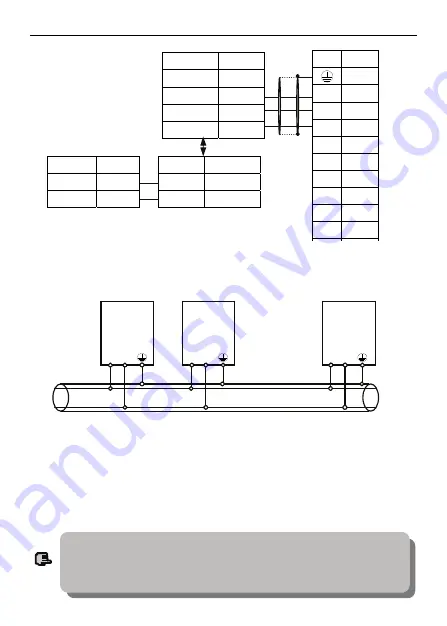
Fig. 3-10 RS485 communication wiring
(4) Multiple inverters can be connected together per RS485 and 31pcs inverter
can be connected together at most. Communication system is more prone to
disturbance as connected inverters increasing, following wiring is recommended:
Fig. 3-11 Recommended wiring for multiple inverters communication
(all inverters and motors well earthed)
Normal communication still not available if using above wiring, can try to take
following measure:
1>
Provide separate power supply for PLC (or upper machine) or isolate its
power supply.
2>
Apply magnetic circle on the communication wire.
3>
Reduce inverter carrier wave frequency properly.
EDS300
CPU board
Mainframe
485A
EDS300
CPU board
Submachine
EDS300
CPU board
Submachine
…
…
485B
485A 485B
485A 485B
Terminal Name
Negative end
B
Positive end
A
Signa
Pin No.
Shell
RXD 2
TXD 3
TXD 3
GND 5
DTR 4
DSR 6
RI 9
CD 1
RTS 7
Terminal Name
Power supply
+5V
Sending TXD
Receiving RXD
5V Grounding
GND
Name Terminal
B
Negative
A
Positive
232/485 Converter
Shielded
cable
(1) When form the network only by inverters, you must set local address parameter F2.15
of the mainframe EDS300 to 0.
(2) For programming of RS485 interface
,
please refer to chapter 7 MODBUS
communication protocol.
Note
ENC


