5 – 26
Section 5 • Maintenance/Service
VSS/VSR/VSM/VSH/VSSH Compressor • Installation, Operation and Service Manual • Emerson • 35391S
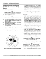
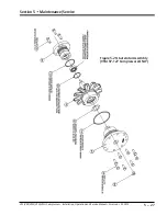
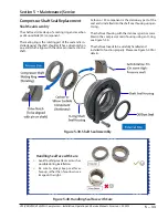
Gaterotor Assembly Replacement
(VSM 97-127 Compressors ONLY)
Removal
1. Remove center member.
NOTE
All parts must be kept with their appropriate side
and not mixed when the compressor is reassembled.
2. Remove bolts from side cover.
NOTE
There will be some oil drainage when the cover is
removed.
3. Turn main rotor so a driving edge of any one of the
main rotor grooves is even with the back of the
gaterotor support.
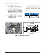
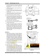
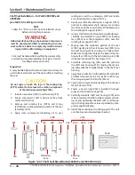
4. Remove the three screws (item 107 in Figure 5-29)
that hold the housing in place.
5. Remove the gaterotor roller bearing housing (item
105 in Figure 5-29).
6. Remove O-ring (102-2), bearing and retainer ring
(106).
7. Remove the 8 screws (107) that hold the ball bear-
ing support (104) and the O-Ring (102-1).
8. To remove the gaterotor support (101), carefully
move support in the opposite direction of rotation
and tilt the roller bearing end towards the suction
end of the compressor. The compressor input shaft
may have to be turned to facilitate the removal of
the gaterotor support.
9. On dual gate compressor units, repeat the proce-
dure for the remaining gaterotor support assembly.
Installation
1. Install gaterotor support by carefully tilting the
roller bearing end of the gaterotor support towards
the suction end of the compressor. The compressor
input shaft may have to be rotated to facilitate the
installation of the gaterotor support. Install gatero-
tor stabilizer. The gaterotor stabilizer (901) will hold
the gaterotor support in place as the thrust bearing
housing is being installed. If the gaterotor support
is not restricted from moving, the gaterotor blade
may be damaged.
2. Install the roller bearing housing (105) with a new
O-ring (102-2), and make sure the O-Ring is in-
stalled in the proper groove.
3. Tighten bolts (107), see Appendix A.
4. Install thrust bearing support. Lubricate the out-
side of the support and bearings with clean com-
pressor oil to aid in the installation. Tighten bolts,
see appendix A.
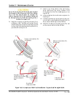
5. Measure clearance between gaterotor blade and
shelf by placing shim stock between gaterotor
blade and shelf until snug. Subtract .003”-.004”
from total amount of shim stock used.
NOTE
This measurement determines the amount of shims
needed for the correct clearance.
6. Use factory installed shim pack (103) and bearing
housing cover without the O-ring.
NOTE
Replacement blades are precisely the same
dimensionally as blades installed originally at
factory: Therefore, the same amount of shims will
be required for replacement blades.
7. Check the clearance between the entire gaterotor
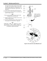
Figure 5-28. Gaterotor Assembly Removal

