5 – 34
Section 5 • Maintenance/Service
VSS/VSR/VSM/VSH/VSSH Compressor • Installation, Operation and Service Manual • Emerson • 35391S
Compressor Shaft Seal Replacement - For
VSS/VSM Units
Tools
Table 5-8. Shaft Seal Tool Kits
Model
(VPN) for the Shaft Seal
Tool Kits
VSM 97 - VSM 127
N/A
VSM 152 - VSM 401
25455A
VSM 501-701
25455B
VSS 291-601
25455B
VSS 751-1301
25455C
VSS 1551-2101
25455D
Removal
1. Remove bolts (281) securing shaft seal housing
(218). to compressor.
NOTE
There will be a small amount of oil drainage as the
shaft seal housing is removed.
2. Insert two of bolts (281) into threaded jacking
holes to assist in removing shaft seal housing (218).
3. Remove mating ring (219C) from compressor shaft.
4. Remove oil seal (230) from shaft seal housing (218).
5. Using a brass drift and hammer, tap out cup as-
sembly (219B) from the back side of shaft seal
housing (218).
6. Remove O-ring (260).
Installation
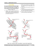
CAUTION
Care must be taken when handling the cup assembly
and mating ring when installing. See Figure 5-40
for handling seal faces with care. Do not touch the
carbon component of the cup assembly or mirror face
on the mating ring as body oil and sweat will cause
corrosion.
NOTE
On VSS 291 - 601 compressors equipped with an
Anti-rotation pin in the shaft seal housing, when
replacing the cup assembly (219B) the Anti-rotation
pin in the housing must be removed. See Figure
5-42.
Suggestion
A spray bottle filled with clean compressor oil may be
used to lubricate the faces of the seals without touching
the seal.
7. Install a new oil seal (230) in seal housing (218).
8. Clean inside shaft seal housing (218) where cup as-
sembly (219B) meets inside shaft seal housing.
9. If applicable, remove protective plastic from cup
assembly (219B).
DO NOT
wipe or touch carbon
component of cup assembly.
10. If carbon component of cup assembly (219B) needs
cleaning, use alcohol and a lint-free cloth to clean.
11. Apply clean compressor lubricating oil to O-ring on
cup assembly (219B).
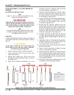
12. Using shaft seal tool or similar, install cup assembly
(219B) in shaft seal housing (218). If applicable,
align the hole on the back of the carbon cartridge
with the Anti-rotation pin in the seal housing. See
Figure 5-42.
13. Clean compressor shaft and shaft seal cavity in
compressor housing.
14. Apply clean compressor lubricating oil to mating
ring (219C) seating area on compressor shaft. See
Figure 5-42.
15. Apply clean compressor lubricating oil to inside
area of mating ring (219C).
IMPORTANT
DO NOT
wipe or touch the face of the mating ring
(219C) where face meets the carbon component of
the cup assembly (219B).
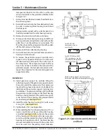
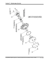
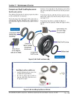
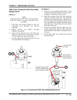
Figure 5-41. Compressor Shaft Seal Assembly
281
218
219B
219C
260
219
230
Carbon Component
Mirror Face

