background image

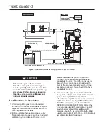
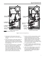
Figure 10.

 Two Way Injection Solenoid Valve - Maintenance

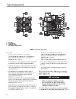
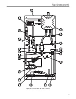
Figure 9. 

Odorant Filter - Maintenance

7

40A

40B

40C

39G

39H

39H

39F

39F

39E

39D

39C

39B

39A

40D

40E

40F

40G

40H

40j

40k

123

LIqUID INLET

LIqUID OUTLET

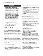
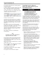
  •   Stop Odorant Recovery Cycle after about 15 

seconds (depending on the installation conditions) 

and eventually repeat the procedure if needed.

  •  Select gas wash time.
  •  Run gas wash cycle.
  •   The cycle will be terminated when the Gas Wash 

cycle time will expire.

  •   Put the system in disable mode and turn it off 

before maintenance operations.

At this point all valves of the system have to be closed 

and you can perform maintenance operations on the 

involved parts.
After completing all operations, to restart the system 

open the system valves, turn ON the odorizer, reset the 

existing alarms and put the system in AUTO (MANUAL 

or MINIMUM RATE).

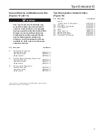
Injection Solenoid Valve Cleaning with 

Liquid Odorant (Injector Flush)

NOTICE

During the washing operation with 

natural gas the control activates both 

injectors at the same time (to increase 

the drying process), during injector  

flush just the selected injector is 

activated. This allows the system to 

increase the pressure for cleaning the 

dirty injector and reduce potential over 

odorization issues. 
For injector selection, please refer 

to Type Dosaodor-D Software for 

Configuration of Type Dosaodor-D 

Odorant Injection System 

Manual (D103117X012).

19

Type Dosaodor-D

Summary of Contents for Tartarini Dosaodor-D

Page 1: ...trolled by Type ROC809 Remote Telemetry Unit for North America Installation Figure 2 Standard Wick Insert Figure 3 Type Dosaodor D Pneumatic Panel Figure 1 Type ROC809 Remote Telemetry Unit Instruction Manual D103102X012 July 2017 Type Dosaodor D ...

Page 2: ... hr 0 89 to 24 97 lbs hr at 6 75 lbs gal Temperature Range 14 to 140 F 10 to 60 C Odorant Calibration Cylinder Body Material 304 Stainless steel Maximum Working Pressure 870 psi 60 0 bar Maximum Emergency Design Pressure 1450 psi 100 bar Solenoid Valves Body Material 304 Stainless steel Gasket Material Fluorocarbon FKM Valve Operation Electromagnetic Maximum Working Pressure 870 psi 60 0 bar Power...

Page 3: ...tion by fixed differential pressure regulators Type SA 2 regulators which reference P2 and reduce the inlet pressure of a regulating station to P2 P Pmin 8 7 psi 0 60 bar Pmax 21 7 psi 1 5 bar an alternate high pressure source can be used This pressure loading of the odorant calibration cylinder filled with odorant is used to inject liquid odorant into the downstream pipeline through an on off val...

Page 4: ...r liquid spillage be prepared to neutralize or contain the liquid Site Requirements Careful consideration when locating the ROC809 on the site can help reduce future operational problems Consider the following items when choosing a location Local state and federal codes often place restrictions on locations and dictate site requirements Examples of these restrictions are the amount of distance fro...

Page 5: ... hydrogen gases or vapors of equivalent nature Group C Atmosphere containing ethylene gases or vapors of equivalent nature Group D Atmosphere containing propane gases or vapors of equivalent nature For the ROC809 to be approved for hazardous locations it must be installed in accordance with the National Electrical Code NEC guidelines or other applicable codes NOTICE Refer to the ROC809 User Manual...

Page 6: ...at activation of magnetic switches in odorant calibration cylinder Use an Ohm meter and validate that when the panel is upright and the float is at the bottom one set of wires has conductivity brown Then tip the panel upside down which will cause the float to slide up the stem to the high level magnetic switch and the second magnetic switch wire should then have conductivity green 3 Get and read t...

Page 7: ...e tank is kept at P2 P pressure then a flow control valve must be installed in the liquid line to control refill time Swagelok flow control metering valves are recommended M and 31 Series Suggested refill time 45 seconds minimum to 120 seconds However if the storage tank floats with the pipeline by using added solenoid valves then this valve is not needed 7 As above refill of the odorant calibrati...

Page 8: ...1 Alarm Output 6 3 IOM3 Channel 2 Low odorant supply tank level Channel 3 Gas volume output pulse Channel 4 Odorant volume output pulse Channel 5 Spare 1 Each module must be inserted in the assigned slot 2 This point should be manually reconfigured if it is not connected to an external flow computer see Dosaodor User Manual D103117X012 Alarm Output Contact Selection Flow Computer Table 2 I O Requi...

Page 9: ...t to give an idea about different configurations and installation options see Figures 4 and 5 the following are the most common 1 Additional odorant flow control valve may be used on odorant liquid line when odorant storage tank is maintained at P2 P P 8 7 to 21 7 psi 0 60 to 1 5 bar CV for built in control valve position 23 Figures 12 13 CV 0 11 Odorant calibration cylinder refill time should be ...

Page 10: ...sible air gas pockets obstacles to the odorant flow Piping should be installed as straight as possible with a constant grade and without any sequences of upward and downward inclines Polytetrafluoroethylene PTFE tape or thread sealer should be used on all pipe fittings to prevent odorant leakage Type ROC809 Controller Installation Planning is essential to a good installation Because installation r...

Page 11: ...on information is provided in the Type Dosaodor D Software for Configuration of Type Dosaodor D Odorant Injection System Manual D103117X012 Refer to the ROC809 Remote Operations Controller Instruction Manual Form A6116 Electrical Connections Schematics The electrical connections between the enclosure and pneumatic panel should be completed according to Figures 7 and 8 Preliminary Checks Before tur...

Page 12: ...Low White Green High Odorant calibration cylinder refill solenoid valve Odorant calibration cylinder solenoid valve A 5 B 6 2 3 4 5 6 1 A 1 B 2 A 3 B 4 7 8 A 7 B 8 Hazardous area Safe area Brown Low White Green High ROC809 Pneumatic Panel Injector 1 solenoid valve Injector 2 solenoid valve Junction box 2 Junction box 1 I S Barrier Remote operations controller enclosure Odorant calibration cylinder...

Page 13: ...osaodor D schematics on Page 12 Junction box 1 C OM 6 8 7 4 5 3 2 1 DI 8 CHAN C H 1 CH 2 CH 3 CH 4 C H Y DO RELA 5 CHAN 5 w gh Com 12 V ble 5 6 7 8 3 4 3 4 12 V 12 V 12 V 12 V Injector 1 solenoid valve Injector 2 solenoid valve Cylinder tank pressure solenoid Cylinder refil control solenoid 6 Injector 1 solenoid valve Injector 2 solenoid valve odorant calibration cylinder tank pressure solenoid od...

Page 14: ...orant input valve found at the base of the pickup tank The use of this valve is strongly suggested for every installation Open the two gas on off valves found on the main line upstream station downstream regulators Using a suitable spray check for any gas leaks check ALL fittings Proceed by switching on the Type ROC809 setting the system in Disable mode Check the line section connecting the pneuma...

Page 15: ...the label value Maintenance and Operation Injection Valve Tuning Procedures and Recommended Timing for Routine Extraordinary Maintenance Operations The Type Dosaodor D system that you have purchased has been manufactured with state of the art technology and materials currently available Type Dosaodor D odorizing system and its accessories are subjected to normal wear aging and must be inspected pe...

Page 16: ...st be calibrated See Screenshot 2 Choose data from Table 3a or 3b according to odorant flow rate and multiply this value for the odorant Specific Gravity Definition Odorant Specific Gravity ρodorant ρH2O ρodorant 8 32 ρodorant Odorant Density LBS Gal ρH2O 8 32 LBS Gal Examples ρSulfur base odorant 8 345 LBS Gal ρMercaptan base odorant 6 776 LBS Gal Screenshot 2 Injection Data Configuration c Odora...

Page 17: ...y the specific gravity of the odorant to be injected typical values range between 0 5 and 1 0 by the value that may be found on the nameplate of the pneumatic panel titled Specific volume injector N 1 These values are listed in right column of above table Example with an odorant specific gravity of 0 6 and the specific volume of injector 1 being 0 0132 lbs sec the entered value would be 0 6 0 0132...

Page 18: ...y and Gas Washing Cycles caution The purging washing operation has to be completed before any routine or extraordinary maintenance intervention and before dismantling the Type Dosaodor D odorizing system During washing operation with natural gas the control activates both injectors at the same time to improve the drying process and reduce time for the operation Only the selected injector is used i...

Page 19: ...you can perform maintenance operations on the involved parts After completing all operations to restart the system open the system valves turn ON the odorizer reset the existing alarms and put the system in AUTO MANUAL or MINIMUM RATE Injection Solenoid Valve Cleaning with Liquid Odorant Injector Flush NOTICE During the washing operation with natural gas the control activates both injectors at the...

Page 20: ... mode refer to Type Dosaodor D Software for Configuration of Type Dosaodor D Odorant Injection System Manual D103117X012 Start the injector Flush Cycle pushing start button refer to Type Dosaodor D Software for Configuration of Type Dosaodor D Odorant Injection System Manual D103117X012 Repeat previous step increasing injector Flush Cycle time if needed according to the needs 1 second is the sugge...

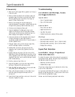
Page 21: ...uctions in paragraph Purge Wash Cycle by Means of Natural Gas Type Dosaodor D Software for Configuration of Type Dosaodor D Odorant Injection System Manual D103117X012 When the operation is accomplished close all on off valves of the system and proceed as follows Slowly loosen the fittings located on the two way injection solenoid valve Remove the connections on the intakes of the two way injectio...

Page 22: ...eassembling 10 Set the spring on top of the nut 11 Align the regulator cover over the body with the sense port opposite the pilot supply port 12 Place the filter pad and screens one on each side of the filter pad on the filter cover 13 Pick up the body and place it on the filter cover with the inlet port aligned vertically with the sense port 14 Insert bolts Place washers and nuts on the end of th...

Page 23: ...imit Alarm The injector has failed and has been placed out of service by the controller The new calculated specific volume for injector is less than 20 of the entered specific volume The system recalculates the specific volume parameter for the injector when the odorant refilling cycle has been accomplished The system triggers an alarm if the calculated value is too low to be compensated by the co...

Page 24: ...nnection fault of high level switch of odorant calibration cylinder 4 Odorant filter is dirty 5 3 way pressure depressure solenoid valve is in fault 6a Filling solenoid valve is faulty 6b Type SA 2 regulator sensing line is partially or completely closed 7 Maximum Odorant Calibration Cylinder Fill time value is too low 8 Ice may have formed preventing odorant flow or movement of level switch float...

Page 25: ... 2 If the system goes to injector alarm the injection valve calibration procedure may be used in extreme cases 3 Odorant calibration refilling should take at least 45 seconds Check odorant tank pressure and or the calibration of flow valve should be mounted in the liquid line to control refill time 4 Check the injector valve ball 5 Use Injector solenoid valve cleaning with Liquid odorant procedure...

Page 26: ... to the low alarm level set by the user 2 If the tank level is User Entered in other words if the user enters an initial tank volume the only time this is checked is at the end of a fill cycle as this should be the only time the volume of the odorant supply tank changes 3 The Current Supply Tank volume value is higher than the Supply Tank Capacity value 1a Check odorant level in odorant supply tan...

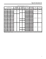
Page 27: ...X12 3 57 0 53 2 M2007360X12 M0301530X12 7 13 1 06 4 M2007360X12 M0301540X12 10 7 1 59 6 M2007360X12 M0301540X12 14 27 2 11 8 3 76 2 M2007379X12 M0301540X12 17 83 2 64 10 M2007379X12 M0301540X12 21 4 3 17 12 4 102 M2007380X12 M0301540X12 24 97 3 7 14 M2007380X12 M0301540X12 0 89 0 13 0 5 870 60 0 2 50 8 M2007360X12 M0301560X12 M4009309X12 M4009310X12 1 78 0 26 1 M2007360X12 M0301560X12 3 57 0 53 2 ...

Page 28: ...90X12 18 Diaphragm GD17446X012 19 Regulator Cover M0239890X12 20 Spring Washer M5001003X12 21 Locking Nut M5006012X12 Pneumatic Panel Figures 12 and 13 Key Description Part Number 1 Panel M0302140X12 4 Junction Box M4009730X12 5 Ball Valve M4006023X12 Three required for B1 version Six required for B2 version 10 Level Switch and Float See Table 5 11 Odorant Calibration Cylinder Junction Box M030151...

Page 29: ...sure Depressure Solenoid Valve Replacing part number M4009297X12 Obsolete part number M4008919X12 Maintenace Kits M4009759X12 39 Two Way Injection Solenoid Valve Replacing part number M2007496X12 Obsolete part number M4008022X12 Maintenace Kits M2201079X12 Two Way Injection Solenoid Valve Figure 10 Key Description Part Number Parts Kit Includes Keys 39C 39E and 39H M2201079X12 39A Valve body M0302...

Page 30: ...me dispositivo di controllo Control device volume Volume specifico iniettore N 1 Volume specifico iniettore N 2 Specific volume injector N 1 Specific volume injector N 2 Pressione massima di comando Maximum drive pressure O M T BOLOGNA ITALY 1450 Bar DOSAODOR D Rev 1 cm 3 cm 3 l h Bar SERIAL N N FABBR OMTTARTARINI S r l Via Paolo Fabbri 1 40013 Castelmaggiore BOLOGNA ITALY 1 31 39 5 34 38 5 24 23 ...

Page 31: ... operating pressure Odorant flow range psi gal h Control device volume gal lb s DOSAODOR D Rev 1 Specific volume injector N 1 Specific volume injector N 2 psi Maximum drive pressure 1450 BOLOGNA ITALY O M T QUESTO IMPIANTO E STATO REALIZZATO DA THIS STATION HAS BEEN CONSTRUCTED BY 31 1 39 5 5 34 39 38 5 5 5 5 19 24 23 22 15 12 10 11 4 31 Type Dosaodor D ...

Page 32: ... express or implied regarding the products or services described herein or their use or applicability All sales are governed by our terms and conditions which are available on request We reserve the right to modify or improve the designs or specifications of our products at any time without notice Emerson Process Management Regulator Technologies Inc does not assume responsibility for the selectio...

Reviews: