


Programming the UC12PG-R Controller on the PMAC II Solo Panel
Overview • 8
1.5.5. Alarms
The UC12PG-R generates logs and alarms that indicate
sensor failures, high enclosure temperatures, and unit re-
boots. Up to 40 alarms can be displayed in the alarm log
list, but an individual alarm must be viewed to see its cur-
rent alarm status (Active or Cleared). Up to four different
alarm types may be listed: (
RH Sensor Error
,
Temp Sen-
sor Fail
,
PMAC High Temp
, and
Normal Power on Re-
set
.)
1.5.5.1. Navigating the Alarm Screens
1. Log into the UC12PG-R as instructed in
2. The Main Configuration screen should be
visible (
). Press the
button to
move the cursor to
3. ALARMS
. Press the
button to select and open the Alarm
screen.
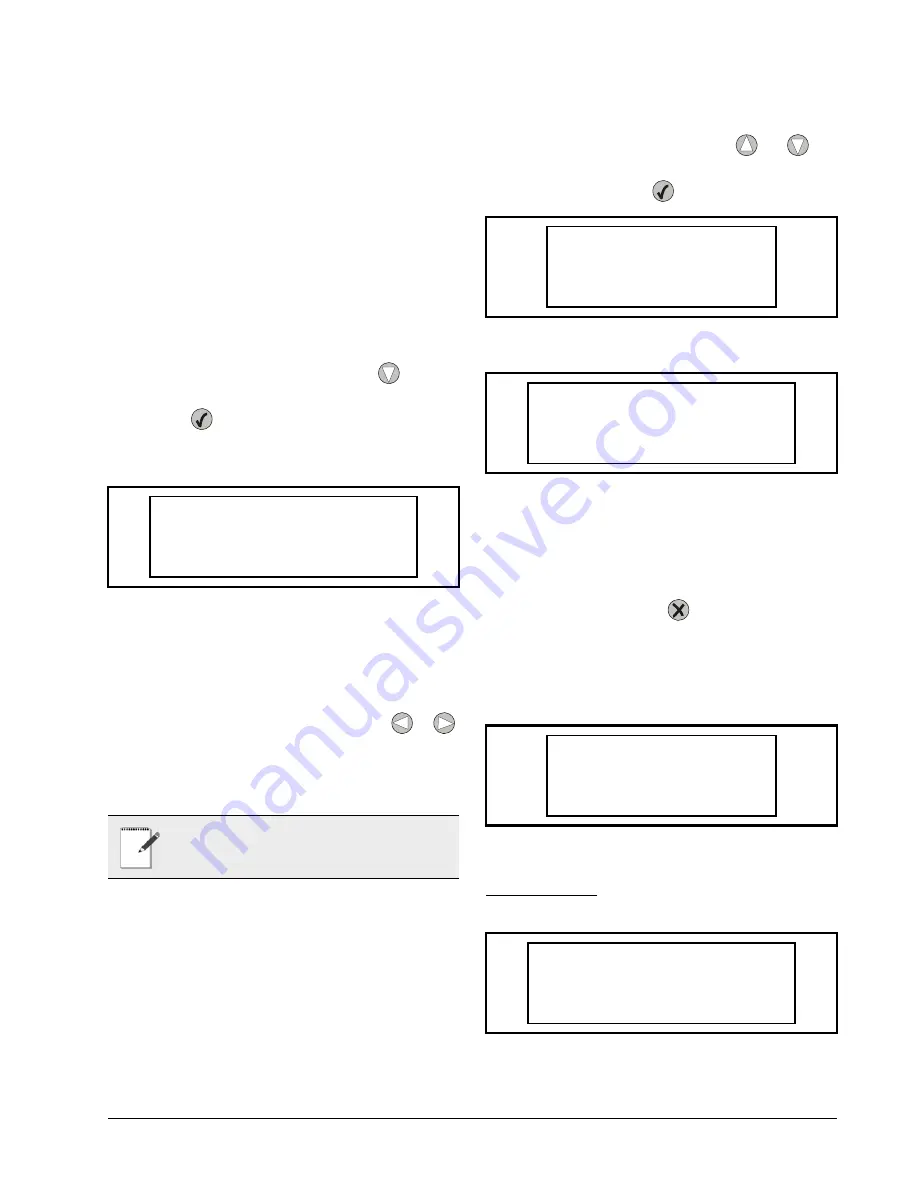
If the
NO ACTIVE ALARMS
message displays, no
alarm history has been generated.
A greater-than "
>
" or less-than "
<
" sign next to the
alarm indicates that the alarm has not been viewed. A sin-
gle brace "
}
" or "
{
" indicates the alarm has been viewed;
however, the alarm may still be active. Use the
or
buttons to scroll sideways to view any text that is not visi-
ble on screen.
1.5.5.2. Viewing the Alarm Screens
3. View an alarm by using the
and
but-
tons to choose an alarm from the alarm log
list. Press the
button to select and view.
The alarm screen (
) shows the number the
alarm appears in the log, the name of the alarm, the time
and date it was recorded, and the alarm status (Active or
Cleared).
4. Once an alarm has been viewed and acknowl-
edged, press the
button to exit the alarm
and go back to the alarm log list. Note that the
greater-than or less-than sign next to the
alarm has now changed to a single brace sign
(
1.5.5.3. Alarm Types
RH Sensor Error
Figure 1-25 - No Active Alarms Screen
NOTE: Alarms are logged and listed in de-
scending order, with the newest alarms num-
bered first in the alarm log.
>NO ACTIVE ALARMS
Figure 1-26 - Alarms List with all Possible Types of Alarms
Figure 1-27 - Viewing an RH Sensor Error Alarm (Cleared)
Figure 1-28 - Alarms List After RH Sensor Error was Viewed
Figure 1-29 - RH Sensor Error Alarm
01>RH SENSOR ERROR
02<TEMP SENSOR FAIL
03<PMAC HIGH TEMP
04>Normal power on r
01>RH SENSOR ERROR
7:49:14 11/12/2003
ALARMS CLEARED
01}RH SENSOR ERROR
02<TEMP SENSOR FAIL
03<PMAC HIGH TEMP
04>Normal power on r
01>RH SENSOR ERROR
7:49:14 11/12/2003
ACTIVE ALARMS
Summary of Contents for PMAC II Solo
Page 2: ......
Page 4: ......
Page 6: ......
Page 20: ...Programming the UC12PG R Controller on the PMAC II Solo Panel Overview 14 ...
Page 21: ......


