


UC12PG-R Output Mapping
Overview • 4
temperature sensor is two-wire, non-polarity specific. Re-
fer to
for wiring to the PMAC II Solo strip.
1.4.
UC12PG-R Output Mapping
shows how the 28 channels of the PMAC II
Solo are connected to the four UC12PG-R outputs.
1.5.
Programming the UC12PG-R
Controller on the PMAC II
Solo Panel
With the sensor properly configured, all that remains to
set up the PMAC II Solo for humidity control is specifying
the minimum and maximum dewpoint setpoints (
), as well as the mini-
mum pulse percentage (
).
1.5.1. Keypad
The PMAC II Solo keypad allows the user to navigate
through all the status and configuration screens and to ad-
just setpoints. The keypad has a four-line display and six
buttons, and can display up to 20 characters on each line.
To exit a screen without saving or to cancel an opera-
tion, press the
button. The
button allows you to se-
lect, enter information, or save changes into the controller.
The
buttons move the cursor and allow
you to change configuration parameters.
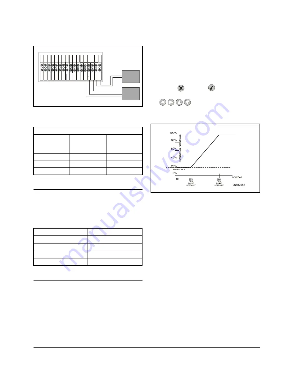
1.5.2. How the Setpoints Work
The PMAC II Solo uses these setpoint values as shown
. When the dewpoint is at or be-
low the Minimum Dewpoint setpoint, the heaters will op-
erate at the percentage specified in the Minimum Pulse
Percentage setpoint. When the dewpoint is between the
minimum and maximum setpoint, the PMAC II Solo’s
pulse percentage varies between the Minimum Pulse Per-
centage and 100% (the higher the dewpoint, the higher the
pulse percentage). Finally, if the dewpoint meets or ex-
ceeds the Maximum Dewpoint setpoint, the heaters will
operate at 100%.
1.5.3. Logging Into the UC12PG-R
All day-to-day user functions, such as viewing alarms
and status screens are performed after being logged into the
system. Viewing and changing any configuration parame-
ters, such as setpoints, minimum pulse times, date, time, or
password, requires the user to enter a six-digit password.
Figure 1-9 - Wiring the Temp & RH Sensor to the PMAC II Solo
RH Sensor
Wire Color
(Belden 8711)
Sensor Ter-
minal Name
PMAC II Solo
Terminal
Strip
Red
PWR
Hu12V
Black
Common
Humidity -
White
RH Out
Hu
Table 1-1 - Wire Colors & Connections for RH Sensor
UC12PG-R Outputs
Anti-Sweat Channels
1
1 - 7
2
8 - 14
3
15 - 21
4
22 - 28
Table 1-2 - UC12PG-R Outputs to PMAC II Solo Channels
Te
m
p
S
en
so
r
Te
m
p
S
en
so
r
H
u
m
id
ity
H
u
m
id
ity
+
H
u
m
id
ity
+
12
V
C
u
rta
il
C
ls
d
=
o
r
C
u
rta
il
C
ls
d
=
o
r
A
la
rm
N
C
A
la
rm
N
C
G
ro
u
n
d
1
20
V
A
C
N
eu
tr
al
E
x
p
B
E
xp
A
E
xp
A
E
xp
B
1
2V
d
c-
12
V
d
c+
1
2V
d
c-
12
V
d
c+
%
O
N
%
O
N
0-
5V
+
0-
5V
-
Indoor Temp Sensor
Indoor RH Sensor
Black
W
h
ite
8641 Cable
White
Black
Red
8771 Cable
P/N 203-5751
Figure 1-10 - Anti-Sweat Control Strategy for the PMAC II Solo
Summary of Contents for PMAC II Solo
Page 2: ......
Page 4: ......
Page 6: ......
Page 20: ...Programming the UC12PG R Controller on the PMAC II Solo Panel Overview 14 ...
Page 21: ......


