background image

Liebert NXL UPS 

Operation and Maintenance Manual 

250-300-400-800kVA 

Page

 81


Event Message 

Event Definition 

Recommended Action 

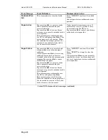
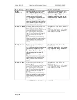
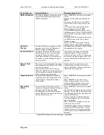
Inlet Ovtemp 

The air flowing into the UPS is too 
warm.  
This alarm is self-clearing. When the 
condition is no longer present, the alarm 
and any control activity tied to the 
alarm reverts to normal.  
 

Press “SILENCE” to silence the audible 
alarm.  
Check the Inlet Air Temperature on the 
One-Line Display and verify the reading 
is accurate, i.e. is the room temperature 
warmer than normal?  
If the room temperature is warmer than 
normal, investigate and resolve the issue.  
If the room temperature is normal, and 
the Inlet Air Temp reading on the One-
Line Display is higher than normal, 
contact your factory-authorized service 
provider.  
 

Excess Auto 
Rexfers 

The UPS has re-transferred too many 
times and is now locked on bypass.  
The UPS attempts to perform an 
automatic transfer back to Inverter, if 
the reason for the transfer to bypass is 
determined by the controls to be 
automatically recoverable; for example, 
a temporary overload.  
The number of times the UPS attempts 
to recover from an automatic transfer to 
bypass is limited.  
When the number of transfers exceeds 
the number allowable (default is 5 
transfers per hour), the UPS remains on 
bypass, and display this message.  
An example of a condition that could 
cause this alarm is cycling load to the 
UPS where the peak load exceeds the 
overload settings. The UPS transfers on 
the overload, re-transfers to Inverter, 
then the overload returns. Once this 
occurs 5 times within one hour, the user 
must manually transfer the UPS back 
online.  
 

Press “SILENCE” to silence the audible 
alarm.  
Press “RESET” to clear any active faults 
or alarms.  
Provided there are no alarms or faults 
still present that could prevent a transfer, 
press “Transfer,” “UPS,” to transfer back 
to Inverter.  
If the transfer is successful, press 
“RESET” to clear the alarm. Otherwise, 
contact your factory-authorized service 
provider.  
 

Excess 
Paralleling 

When the controls detect a high 
amplitude, short duration overload 
condition on the output, the static 
switch is turned on momentarily in 
parallel with the Inverter to attempt to 
clear the condition.  
If the fault clears, the controls turn off 
the static switch and the load remains 
on Inverter. This fault condition 
indicates the UPS pulse paralleled too 
many times and is now locked on bypass 
(auto re-transfers to Inverter are 
inhibited).  
 

Press “SILENCE” to silence the audible 
alarm.  
Check the Module Output Meter and 
verify the output currents are normal, the 
kVA/kW percentages are less than 100%, 
and the Rexfer Timeout is 00:00.  
Verify the Inverter box on the One-Line 
Display is green.  
Investigate any other active alarms or 
faults before attempting to clear this 
fault.  
Press “RESET” to clear the fault.  
If the Event Window is clear, press 
“Transfer,” “UPS” to transfer the load 
back to Inverter.  
If the “UPS” button is grayed out, or 
pressing the “UPS” button does not 
transfer the unit back to Inverter, or if 
the UPS immediately transfers back to 
bypass, contact your factory-authorized 
service provider.  
 

Liebert NXL alarm and status messages (continued) 

Summary of Contents for Liebert NXL series

Page 1: ...AC Power For Business Critical Continuity Liebert NXL Operation and Maintenance Manual 250 to 800kVA 50 60Hz Three Phase Single Module and 1 N ...

Page 2: ...Page ii ...

Page 3: ...ep your Liebert UPS and your systems permanently at their peak performance If you already own and use a Liebert UPS then we are doubly honoured by your decision to continue this valued relationship It is our constant endeavour to partner you to ensure the growth success of your business our philosophy is reflected in our mission statement Keeping Business in Business Please give us your valued fee...

Page 4: ...k Power No warranty of accuracy is given concerning the contents of the information contained in this publication To the extent permitted by law no liability including liability to any person by reason of negligence will be accepted by Emerson Network Power its subsidiaries or employees for any direct or indirect loss or damage caused by omissions from or inaccuracies in this document Emerson Netw...

Page 5: ... 3 3 Input Power Failure Load on Battery 36 2 3 4 Off Battery 37 2 3 5 Emergency Power Off EPO 38 2 3 6 Remote Emergency Power Off REPO 38 2 4 Manual Procedures 39 2 4 1 Startup Procedure 39 2 4 2 Load Transfer Procedures 42 2 4 3 Maintenance Bypass Load Transfers 43 2 5 Shutdown Procedures 45 2 5 1 Module Shutdown Procedure 45 2 6 Automatic Operations 46 2 6 1 Overloads Without Transfer 46 2 6 2 ...

Page 6: ...5 Figure 3 Main Display screen typical 16 Figure 4 Mimic display 16 Figure 5 Monitor mimic display example Normal power flow 17 Figure 6 Monitor mimic display example Utility fail 17 Figure 7 Monitor mimic display example Load on bypass UPS On 18 Figure 8 Monitor mimic display example Load on bypass UPS module Off 18 Figure 9 Menu tree 19 Figure 10 Rating Parameters 20 Figure 11 System Settings pa...

Page 7: ... transfers 43 Figure 37 Current versus time curves of overload capacity 46 Figure 38 Manual Start to Bypass 50 Figure 39 Manual Start to Bypass one or more modules 50 Figure 40 Rectifier ON command 51 Figure 41 Load on Bypass UPS available 51 Figure 42 Load on Bypass BCB closed 52 Figure 43 Load on UPS 52 Figure 44 Parallel System view 53 Figure 45 Starting 1 N System Shutdown 55 Figure 46 1 N Sys...

Page 8: ...tribution to informed partners Installation restrictions or additional measures may be needed to prevent disturbance See EN 62040 2 If you encounter any problems with the procedures contained in this manual you should seek immediate assistance from the Liebert Sales Office from whom the equipment was purchased Alternatively contact the Emerson Network Power s Customer Service Support department at...

Page 9: ...your area For areas not covered by Liebert Services the authorized distributor is responsible for providing qualified factory authorized service If you require assistance for any reason please have the following information available Model and size Part number Serial number Date installed Location Voltage Frequency Battery reserve time Requests the user to read the note ...

Page 10: ...r shutdown Check with a voltmeter before making contact AC voltage will remain on the system bypass the UPS output terminals and the static bypass switch unless associated external circuit breakers are opened Check for voltage with both AC and DC voltmeters prior to making contact When the UPS system is under power both the operator and any test equipment must be isolated from direct contact with ...

Page 11: ...erts that DC power from the utility or DC power from the batteries into AC power for the load The batteries power the load through the inverter in the event of a power failure The utility source can also power the load through the static bypass If maintenance or repair of the UPS is necessary the load can be switched without interruption in service to the maintenance bypass Figure 1 Typical UPS sy...

Page 12: ...the load from the inverter to the bypass WITH interruption in AC power to the critical load This interruption will be less than 20ms This interruption time may be modify through Bypass Transfer Setpoint Menu for Service only 1 2 3 Battery Mode When utility AC power fails the Liebert NXL protects the critical load by instantaneously channelling battery power to the inverter which continues supporti...

Page 13: ...moved from the UPS system This option is required to complete the UPS system Input Current Distortion Filter This filter reduces input current reflected harmonic distortion THD at full load The filter is factory installed in the UPS This filter also improves the input power factor at full load External Maintenance Breaker This switchboard provides make before break maintenance bypass It includes M...

Page 14: ...edures Check status reports and history files Adjustment programmable parameters access limited by security access function Adjustment output voltage before performing a manual load transfer The touch screen is a white background display with multicolor text The display turns on automatically but after 15 minutes of inactivity the backlight will go out and the display will appear very dim Touching...

Page 15: ...age 15 Figure 2 Main component locations 1 2 3 4 5 6 1 Input isolator Q1 2 Bypass isolator Q2 3 Maintenance bypass isolator Q3 4 Output isolator Q4 5 Options box Intellislot housings 6 HMI Screen External interface board EIB Emergency Power OFF EPO 250 300 400kVA 800kVA ...

Page 16: ... from the battery Pressing this icon switches among the connected battery strings The Module Battery Disconnect BCB is to the right of this block The circuit breaker status is shown as open or closed DC Bus Displays the DC Bus voltage and the state of the battery charger Load Displays the output line voltage phase voltage current kVA kW power factor and frequency The critical load current per phas...

Page 17: ...d Maintenance Manual 250 300 400 800kVA Page 17 Figure 5 Monitor mimic display example Normal power flow Figure 6 Monitor mimic display example Utility fail Line colour means Green Normal Orange Marginal Gray Absent Black Unknown ...

Page 18: ...nce Manual 250 300 400 800kVA Page 18 Figure 7 Monitor mimic display example Load on bypass UPS On Figure 8 Monitor mimic display example Load on bypass UPS module Off Line colour means Green Normal Orange Marginal Gray Absent Black Unknown ...

Page 19: ...om the main display screen see Figure 3 These menu items are detailed in subsequent sections Figure 9 Menu tree 2 2 2 Help This button will display the help menu 2 2 3 Metering This button will place the metering tables in the multipurpose window 2 2 4 Silence This button will silence the audible alarm 2 2 5 Reset This button will reset any non active latched events ...

Page 20: ...PS is installed Nominal Input Voltage Nominal Bypass Voltage Nominal Output Voltage Nominal Source Frequency Nominal Output Frequency Nominal Cell Count Output kVA Output KW Configuration Type Rectifier Type Input Isolation Transformer Unit Model Unit Serial Maintenance Bypass Model Maintenance Bypass Serial Battery Cabinet Model Battery Cabinet Serial Order Number 1 Order Number 2 Service Telepho...

Page 21: ...tness High or Low default Low Time 24hr format Adjust Hour Minute or Seconds Date MM DD YYYY format Adjust Month Day or Year Password Reset the password 4 characters alphanumeric case sensitive Language English Chinese French Spanish German Italian Portuguese Audio level Range 1 to 10 default 5 Phase labeling Auto ABC RST XYZ RYB RWB UVW 123 L1L2L3 default Automatic Unit Locator Location ID Alphan...

Page 22: ...arameter to be changed Max Load Alarm Phase A 10 to 105 default 100 Phase B 10 to 105 default 100 Phase C 10 to 105 default 100 Delay second 0 to 60 default 5 seconds Manual Xfer Bypass Voltage Limits Manual Xfer Bypass Voltage Low Limit 1 to 20 default 10 Manual Xfer Bypass Voltage High Limit 1 to 15 default 10 Figure 12 Adjustable setpoints parameters Inlet Air Temp Warning Inlet Air Temp Warnin...

Page 23: ...rvice to be functional If Battery Equalize is disabled the feature will not be available and the menu item will not be displayed Figure 13 Battery Equalize settings Battery Test Auto Test Enable Disable default disabled Test Cycle weeks 1 to 26 default 13 weeks Time of day hh mm Set Hour and Minute sets the start time of the automatic battery test Start Date mm dd yyyyy Set Month Day and Year Test...

Page 24: ... Battery Temperature Battery Temp Warning 30 C to 50 C default 40 C Battery Temp Limit 35 C to 60 C default 50 C Disconnect Enable Disable default disabled NOTE If Disconnect is set to Enable and the Battery Temp Limit is met the Battery breaker will open Cell Count Adjustment Cell Count Adjustment 12 cells to 6 cells default 0 Float Voltage Battery Float Voltage Vpc 2 15 to 2 3 default 2 25 ...

Page 25: ...ed for the following Latch yes no Event stays active in the event window even if the fault condition has been cleared until user acknowledges it by pressing the Reset button Audible yes no Will set Audible alarm when event occurs Event log yes no Will display event in Event log when it occurs NOTE You must press Save for changes to take effect See Table 6 for a list of alarms fault and status mess...

Page 26: ...tems must be enabled by service to be functional Load Bus Synch Enable Disable default disable Figure 16 Load Bus Sync not available on the display screen Input Contact Isolator Board Assignment Custom Pre assigned default Input Contact XY Delay sec 0 to 99 9 default 0 Message Custom 0 19 characters Figure 17 Input Contact Isolator Board screen ...

Page 27: ...ebert NXL UPS Operation and Maintenance Manual 250 300 400 800kVA Page 27 Programmable Relay Board Assignment 0 to 4 event default 0 Delay sec 0 to 99 9 default 0 Figure 18 Programmable Relay Board screen ...

Page 28: ...time date stamped events are captured in the log The oldest record will be overwritten with a new record once the buffer reaches 2048 events Figure 19 Event Log 2 2 7 2 2 2 7 2 2 2 7 2 2 2 7 2 System Status System Status Total Operating Hours Total number hours the UPS has been operational Battery Operating Time A running total of the battery discharge time for all events since the log was last cl...

Page 29: ...2 8 2 Device control Devices Close Trap This will start the Input filter if installed Close BCB The Close command will Enable the breaker UVR The BCB must be closed manually If no BCB is selected do not display this setting 2 2 9 Shutdown Menu This menu permits shutting down the UPS and individual devices Figure 20 Shutdown menu 2 2 9 1 2 2 9 1 2 2 9 1 2 2 9 1 Open Input Trap filter Open Trap Open...

Page 30: ...shut down To shut down the UPS an operator must press OK Figure 21 UPS shutdown popup 2 2 9 4 2 2 9 4 2 2 9 4 2 2 9 4 UPS OFF System Turns off inverter rectifier static switch and trips all battery breakers Will shutdown UPS completely NOTICE NOTICE NOTICE NOTICE Risk of equipment damage This command will result in the load being shut down The following popup window is displayed when the UPS is ab...

Page 31: ... pressing Bypass will switch the UPS to Bypass mode Pressing UPS will switch back to Normal Inverter Mode see Figure 23 Figure 23 Transfer retransfer commands 2 2 11 Battery Management Menu This menu permits configuring battery settings 2 2 11 1 2 2 11 1 2 2 11 1 2 2 11 1 Time Remaining Graph Time Remaining Graph Displays the time remaining graph in the multipurpose window plot the battery voltage...

Page 32: ...me remaining display 2 2 11 2 2 2 11 2 2 2 11 2 2 2 11 2 Manual Battery Test Manual Battery Test Start Stop 2 2 11 3 2 2 11 3 2 2 11 3 2 2 11 3 Manual Battery Equalize Manual Battery Equalize For Service only 2 2 11 4 2 2 11 4 2 2 11 4 2 2 11 4 Commissioning Commissioning For Service only ...

Page 33: ...y Cycle Monitor Displays how many discharges have occurred for these time periods 0 30sec 31 90sec 91 240sec 4 15min 15 30min 30 60min 60 240min 4 8hrs 8hrs and up Each discharge record will include see Figure 25 Max KW Date AH Time Start Temp C Duration End Temp C Start kW Battery CB Start Min kW Battery CB End Figure 25 Battery cycle monitor ...

Page 34: ...ime Active Battery Discharge Time Active Battery Amp Hours Active Battery KW Total Number of Discharges Figure 26 Battery cycle monitor summary Clear Log This command resets the Date of First Discharge Cycle A dialog box will warn that the data will be permanently lost and should downloaded before proceeding see Figure 27 Figure 27 Battery cycle monitor clear log ...

Page 35: ...tions do not show an alternate power source generator and automatic transfer switch external to the UPS that might be present at your installation 2 3 1 Load on Bypass Load on Bypass with the UPS not available is shown in Figure 28 The UPS system could be in this mode of operation during either initial start up or UPS shutdown NOTICE NOTICE NOTICE NOTICE Risk of equipment damage When the critical ...

Page 36: ...pass to the UPS To perform a manual transfer Use the Load Transfer Procedures screen Refer to 2 4 2 Load Transfer Procedures The UPS control logic will initiate an automatic transfer to bypass if an overload condition exceeds the system current versus time window or if a UPS fault is detected The control logic may initiate an automatic retransfer to the UPS system when the system is recovering fro...

Page 37: ... block in the UPS module Monitor Mimic Display indicates Charge or Discharge and the current in amperes Figure 31 Input power fail load on battery 2 3 4 Off Battery The battery plant can be disconnected from the UPS if required for battery maintenance by opening the module battery disconnect BCB circuit breaker In this situation the UPS module will continue to supply conditioned power to the criti...

Page 38: ... Power OFF 2 3 6 Remote Emergency Power Off REPO The Remote Emergency Power Off control is a user provided switch located remotely from the UPS system It usually is installed in the same room as the critical load equipment This mode can also be initiated by an automatic contact closure in the same external circuit as the manually operated switch When the Remote Emergency Power Off switch is operat...

Page 39: ... from UPS to bypass and retransfers from bypass to the UPS system Maintenance Bypass Load Transfers including transferring from internal bypass to maintenance bypass and transferring from maintenance bypass to internal bypass Shutdowns including module shutdowns for maintenance and emergency shutdowns NOTE The following procedure assumes that the UPS installation inspection and initial start up ha...

Page 40: ...n NOTE If the system was shut down in response to an Emergency Off there may be alarm messages on the touch screen that describe system conditions before or at the time of the shutdown Some or all of the alarm conditions may have been resolved To clear these alarm messages turn off control power see Figure 2 Wait at least 10 minutes for the control power circuitry to completely de energize After 1...

Page 41: ...dule Battery Device if elec trip breaker is enabled when you press OK then the battery connect into system if set to manual breaker after you press OK the system will show that please close the BCB Load is still on internal bypass i The Press OK to Issue Transfer Command message appears Press OK The load is now energized from the UPS Inverter NOTICE NOTICE NOTICE NOTICE Risk of equipment damage If...

Page 42: ... 1 2 4 2 1 2 4 2 1 Transfer Procedure 1 Press the Transfer menu button on the touch screen 2 The Transfer Retransfer screen will appear in the multipurpose window see Figure 23 3 If the UPS output is with synchronization with the bypass press the Bypass button This will transfer the load from UPS to Bypass 2 4 2 2 2 4 2 2 2 4 2 2 2 4 2 2 Re Transfer Procedure 1 Press the Transfer menu button on th...

Page 43: ...nd the UPS module inverter output Use the Monitor Mimic Display screen to verify the UPS bypass line is available Figure 36 Maintenance bypass transfers NOTICE NOTICE NOTICE NOTICE Risk of equipment damage Failing to follow the proper operating sequence when operating any circuit breaker may cause damage to the connected equipment Operating a Maintenance Bypass isolator out of sequence could cut o...

Page 44: ... not protected from normal supply aberrations when operating in the maintenance bypass mode 3 Open the following isolators Q1 Q2 and Q4 The UPS system is now isolated from the critical load and the load is now on Maintenance Bypass mode 2 4 3 2 2 4 3 2 2 4 3 2 2 4 3 2 Maintenance Bypass Load Transfers If Load is on Maintenance Bypass 1 Close the Bypass isolators Q2 and Q4 Refer to 2 5 1 Startup Pr...

Page 45: ... of the UPS module 2 5 1 1 2 5 1 1 2 5 1 1 2 5 1 1 UPS Shutdown Procedure NOTE This shutdown turns Off the inverter rectifier and trips all battery breakers Transfers to bypass if available 1 Press the Shutdown menu button on the touch screen The Shutdown screen will appear in the multipurpose window see Figure 19 2 Press the UPS button This brings up a warning dialog box see Figure 20 3 Press OK ...

Page 46: ... an automatic transfer to bypass and emergency module shutdown when specified UPS faults occur 2 6 1 Overloads Without Transfer The UPS system is capable of sustaining full output voltage 2 of the nominal voltage for overload conditions that remain within under the current versus time curve of overload capacity Figure 37 Note that the time scale is not linear For high current demands of short dura...

Page 47: ...nds Because of the reliability of the UPS components an interrupted load transfer is a very unlikely occurrence 2 6 3 Automatic Transfers to Bypass UPS System Faults For specified UPS system faults the control logic will initiate an automatic transfer to bypass followed immediately by a shutdown and isolation of the UPS system The following UPS system faults will initiate an automatic transfer to ...

Page 48: ...any condition other than output overload 2 Both output power and current have since dropped below 101 of the rated load 3 Both the Input isolator and the Battery BCB circuit breaker have remained closed since the overload transfer 4 OK to Transfer signal received from the control logic 5 Cyclic type overloads which occur up to five select range is 0 to 5 times in 60 minutes are automatically retur...

Page 49: ...ad to bypass and shutting down Perform each step of the procedure in every UPS module before proceeding to the next step 2 7 3 Preliminary checks Be sure that the modules are the same rating and with the same firmware release 2 7 4 System start up This procedure should be followed when turning on the UPS from a fully powered down condition i e where the load is not being initially supplied at all ...

Page 50: ...s 4 After pressed the OK button then can choose this module only start this module on bypass and all modules start all modules on bypass as shown in figure below Figure 39 Manual Start to Bypass one or more modules 5 Press either All Modules or This Module then the load is on bypass as shown in figure below ...

Page 51: ...ure 40 Rectifier ON command 6 Start rectifier After bypass started then enter the process of starting rectifier on the LCD as shown in figure above Rectifier section will be green Press Ok button then rectifier start as shown in figure below Figure 41 Load on Bypass UPS available ...

Page 52: ...utton the system will show that you can manually close the BCB After that the battery is connected successful as shown in figure below Figure 42 Load on Bypass BCB closed 8 The parallel system transfer to UPS After inverter started and the battery is connected into system and all module s voltage and frequency of inverter output sync with the bypass of this parallel system the LCD shows the figure...

Page 53: ...s In the figure below are shown the breakers of the System Paralleling cabinet option the figure below is for 1 1 parallel system Figure 44 Parallel System view 10 Add new module into the parallel system if a module need to be added after the parallel system is running enter the process of start up rectifier and inverter directly so this module can be added UPS on the mode that inverter supply the...

Page 54: ... case of fixing completed and have tested by authorization of Liebert Services engineer all of the power breaker outside were closed 1 Open confirm opened the breaker of maintenance bypass Q3 and BCB 2 Close the breaker of bypass Q2 Q4 output breaker and the outside output breaker if exist 3 Close the breaker of input Q1 start up rectifier and inverter directly refer the operations of SMS 4 Connec...

Page 55: ...ual 250 300 400 800kVA Page 55 Figure 45 Starting 1 N System Shutdown 2 If press 1 N UPS button and press Ok then shutdown all of the UPS modules and parallel system transfer to bypass as shown in next figure Figure 46 1 N System Shutdown confirm ...

Page 56: ... single module system SMS or 1 1 redundant multimodule UPS applications External located in the SPC for 1 1 capacity and 1 N redundant multimodule UPS applications IMPORTANT With configurations consisting of two UPS s 1 1 capacity or 1 N redundant systems integrated with more than two UPS s where the load level is above the rated power of the single UPS it is necessary to install an adequate exter...

Page 57: ...aking contact AC voltage will remain on the bypass and output isolators and the static bypass switch unless associated external circuit breakers are opened Check for voltage with both AC and DC voltmeters prior to making contact When the UPS system is under power both the operator and any test equipment must be isolated from direct contact with earth ground and the UPS chassis frame by using rubbe...

Page 58: ...e entire battery system to ensure it meets current standards Maintenance Agreements The Signature Program UPS Service Agreements Liebert Services LGS has a variety of available maintenance agreements depending on specific site needs Choose the level of support appropriate for each installation Mission critical sites can have the standard parts and labor around the clock coverage for their UPS with...

Page 59: ...east annually thereafter Keep it inspected Periodically inspect external upstream switches and downstream isolators to assure that the trip current settings are correct Become familiar with typical ambient conditions surrounding equipment so that abnormal conditions may be more quickly recognized Know what typical meter readings are and where adjustable settings should be 3 3 1 Record Log Set up a...

Page 60: ... site specific requirements maintenance and other environmental conditions that affect the length of the component s useful life cycle Component Expected Life Replace in Power AC filter capacitors 7 years 62 000 hours 5 to 6 years Power DC filter capacitors 7 years 62 000 hours 5 to 6 years Low profile fans 7 years 62 000 hours 5 to 6 years Air filters 1 to 3 years Check four times per year Batter...

Page 61: ...ral state and local regulations Because lead is a toxic substance lead acid batteries must be recycled rather than discarded Do not dispose of battery or batteries in a fire The battery may explode Do not open or mutilate the battery or batteries Released electrolyte is harmful to the skin and eyes It is toxic WARNING Risk of electrical shock and high short circuit current Can cause equipment dama...

Page 62: ...olyte levels is not required visual inspections and checks of battery voltage and connection resistance should be made NOTICE NOTICE NOTICE NOTICE Risk of equipment damage Batteries should be cleaned with a dry cloth or a cloth lightly moistened with water Do not use cleaners on the batteries Solvents can make the battery cases brittle Because individual battery characteristics are not identical a...

Page 63: ...age should be no less than the value shown while the recorded float voltage should be within the range shown If a discrepancy is found contact Liebert Services Table 2 Battery voltage nominal and float Battery Voltage VDC UPS kVA Number of Cells 400V Nominal Float 250 300 400 198 396 446 800 240 480 540 Power Connections Check for corrosion and connection integrity Visually inspect wiring for disc...

Page 64: ... of the average input current Alarm messages indicate malfunction or impending malfunction A daily check of the Display Screen will help to provide an early detection of problems Refer to Table 6 for information about interpreting alarm messages Tracing a problem to a particular section is facilitated by alarm messages and the metered parameter indications NOTICE NOTICE NOTICE NOTICE If the UPS sy...

Page 65: ... is designed for indoor use only and is not to be subjected to falling objects or precipitation Recommended Operating Temperature C 25 ambient Maximum Operating Temperature C 40 ambient design temperature without derating see Notes 2 and 3 Minimum Operating Temperature C 0 C Storage Temperature C 25 to 70 Typical Battery Temperature Requirements Average annual temperature must not exceed 27 C Peak...

Page 66: ...ntrolled Output Power kW 225 270 360 Output Voltage Vac 380 400 default 415 3 ph 4 wire plus ground Output Voltage Regulation 1 3 phase RMS average Output Voltage Regulation 100 Unbal Load 2 3 phase RMS average Output Frequency Hz 50 Output Frequency Regulation 0 1 Output THDu at Nominal Voltage Linear Load 2 Output THDu at nominal voltage Including a 100kVA Non Linear Load per EN 62040 3 2 5 max ...

Page 67: ...ic emission and immunity 61000 series and construction 60529 Electrical Specifications 250 300 400kVA UPS continued Disclosures with Regard to Embedded Software Licensed from TrollTech Inc Sublicensed Software 1 Limits on Use Distribution and Derivative Works User is not given any rights to modify or create derivative works based on Sublicensed Software or reproduce Sublicensed Software or distrib...

Page 68: ... parameters here it is assumed that extremes of all the conditions do not apply simultaneously 380 400 415 400V default 3 phase 3 wires plus ground 800 Input THDi at nominal voltage at full load Input Power Factor at nominal voltage 320 20 to 460 15 1270 Optional 540 Vdc 380 400 415Vac 1 RMS value 3 4 Vpp Selectable from 1 60 to 1 88 for VRLA Wet Cells 2 30 adjustable in 0 01 volt increments from ...

Page 69: ...taneously Altitude de rating with OR without input harmonic filter IEC 62040 1 1 IEC 62040 2 IEC 62040 3 Physical Parameters Standards Environmental Parameters 25 to 70 Operating Temperature Range 1 Max kW derate per 100m rise above 1500 m or temp derate of 1 C 100m between 1500 3000 m ZP 7021 1500 as per IEC 62040 3 More than 180 1950 IP 20 even with front door in opened condition 78 0 to 95 non ...

Page 70: ...he only alarm present attempt a manual start of the unit by pressing Startup Manual Start then following the prompts to attempt to place the unit back online If the manual start fails or if there are other alarms present that won t clear contact your factory authorized service provider Auto Rexfer Failed The condition that caused an automatic transfer to bypass failed to clear within a specified t...

Page 71: ...if available and contact your factory authorized service provider Batt Equalizing The batteries are being equalized Battery equalization stops automatically based on the Equalize Time Setting This status message is self clearing When the condition is no longer present the message and any control activity tied to the status event reverts to normal In normal operation no user response is required Eq...

Page 72: ...mperature limit is being reported correctly investigate potential causes such as faulty air conditioning or air flow blockage and resolve Otherwise contact your factory authorized service provider Batt Ovtemp Warning One or more of the Battery Temperature Sensors is reporting a temperature above the warning setpoint There are two user adjustable Battery Temperature Setpoints Battery Over Temperatu...

Page 73: ...e Line Display Cycle through all connected batteries by pressing the Battery Box on the display Contact your factory authorized service provider Batt Temp Imbalance With more than one Battery Temperature Sensor installed the controls are detecting too great a temperature difference between the individual sensors Press SILENCE to silence the audible alarm To attempt to identify which sensor is repo...

Page 74: ...tor is to prevent leakage current through the bypass circuit during an outage This status message is self clearing When the condition is no longer present the message and any control activity tied to the status event reverts to normal This status message is informational If the isolator was not opened intentionally or if the isolator is actually closed and this message is active contact your facto...

Page 75: ... closed If a breaker that should be open shows closed or if the breaker in question actually is open but the fault is still present attempt to clear the fault by pressing RESET If the event does not reset contact your factory authorized service provider Byp Overload Ph A Byp Overload Ph B Byp Overload Ph C The critical load is greater than 110 while the UPS is on bypass The controls may shut the u...

Page 76: ...till present contact your factory authorized service provider If there is a problem indicated with the bypass voltage investigate and resolve the issue Examples of conditions that could cause this alarm Unstable generator voltage or Bypass isolator opened Bypass OF UF The bypass frequency has exceeded the bypass frequency limit of 5 Hz of nominal If this alarm is active transfers to bypass are dis...

Page 77: ...tteries connected the most likely cause of a current path to ground is a leaking battery If your system includes an optional Battery Ground Fault Monitor check if the Battery Ground Fault message is present also Press SILENCE to silence the audible alarm Press RESET to clear the fault Perform a visual inspection of the batteries Look for signs of leaking battery acid or excessively corroded batter...

Page 78: ... summary event indicates the UPS is nearing an over temperature condition Depending on which sensor is reporting the high temperature the UPS may do one of three things once the limit is reached shut down transfer to bypass or transfer to battery operation This is a potentially serious event Investigate possible causes for a rising temperature condition such as loss of air conditioning airflow obs...

Page 79: ...ify the bypass line is green If it is not contact your factory authorized service provider immediately and prepare to shut down the load b If external Maintenance Bypass is available close the Maintenance Bypass Breaker MBB to place the load on Maintenance Bypass Do not attempt to re transfer to UPS without first contacting your factory authorized service provider c If external Maintenance Bypass ...

Page 80: ...tude short duration overload condition on the output the static switch is turned on momentarily in parallel with the Inverter to attempt to clear the condition If the fault clears the controls turn off the static switch and the load remains on Inverter This fault condition indicates the UPS pulse paralleled too many times and is now locked on bypass auto re transfers to Inverter are inhibited Pres...

Page 81: ... re transfers to Inverter then the overload returns Once this occurs 5 times within one hour the user must manually transfer the UPS back online Press SILENCE to silence the audible alarm Press RESET to clear any active faults or alarms Provided there are no alarms or faults still present that could prevent a transfer press Transfer UPS to transfer back to Inverter If the transfer is successful pr...

Page 82: ...ut wiring was connected incorrectly This alarm is self clearing When the condition is no longer present the alarm and any control activity tied to the alarm reverts to normal Press SILENCE to silence the audible alarm Verify correct phase rotation at the input If the phase rotation is correct contact your factory authorized service provider Input Contact XY The displayed text for this alarm is dep...

Page 83: ...n the condition is no longer present the alarm and any control activity tied to the alarm reverts to normal Press SILENCE to silence the audible alarm Observe the meters on the One Line Display for input voltage level battery charge discharge current and output load percentage kW Investigate any abnormal readings If the reason for the alarm cannot be determined contact your factory authorized serv...

Page 84: ...e One Line Display in response to this alarm and indicates the time remaining until a transfer to bypass occurs The length of time remaining until transfer is directly proportional to the severity of the overload This alarm is self clearing When the condition is no longer present the alarm and any control activity tied to the alarm reverts to normal Press SILENCE to silence the audible alarm Check...

Page 85: ...t and inhibits normal start up of the UPS Press SILENCE to silence the audible alarm Turn off Control Power to clear the event Wait 5 minutes before re applying Control Power If the fault fails to clear contact your factory authorized service representative LBS Inhibited With LBS operation enabled conditions required to allow LBS operation are not met Voltage or Frequency differences sensed by the...

Page 86: ...s SILENCE to silence the audible alarm To clear this alarm verify all battery breakers are closed Investigate any open breakers Low Batt Shutdown The Battery has reached End of Discharge EOD There is no longer enough energy left in the battery to run the Inverter with the current load If bypass is available the UPS attempts to transfer the load to bypass at EOD Press SILENCE to silence the audible...

Page 87: ...rol the output power factor Press SILENCE to silence the audible alarm Evaluate the load on the UPS For more information contact your factory authorized service provider Main Control Fault The UPS has transferred to Bypass due to a loss of communications with the Main Controller All Transfers Startup Shutdown and Metering screens are locked out The Controls attempt to reestablish communications bu...

Page 88: ...Event Window when manual transfers are enabled A possible reason for this condition is an unstable generator If the generator frequency is not stable or not at 50 Hz the Inverter may have difficulty maintaining synchronization with the bypass source To check the synchronization of the Inverter to bypass click Transfer and observe the synchroscope A non sync condition is indicated by a varying phas...

Page 89: ...ive contact your factory authorized service provider Outlet Ovtemp Limit The difference between the inlet air temperature and the outlet air temperature is too great This alarm means excessive heat is being generated internally resulting in a higher than normal exhaust air temperature If the Bypass is within limits the UPS reacts to this alarm by transferring to Bypass and shutting off the Inverte...

Page 90: ...potentially serious condition in the Rectifier circuit The controls respond to this by turning off the Rectifier opening the input filter contactor and placing the UPS on battery operation This fault is non latching When the underlying condition is no longer present this fault and any control activity tied directly to this fault reverts to normal Observe the One Line Display and the Active Event W...

Page 91: ...generation Mode contact your factory authorized service provider Regen Failure Regeneration Mode was initiated and terminated because of an abnormal condition Once Regeneration Mode is active any condition for example an Inverter Overload other than the user manually stopping Regeneration Mode causes this message to appear Regeneration Mode is a service mode that is normally controlled by the serv...

Page 92: ...reverts to normal Check the state of the Remote Off BPSS signal If this signal is not active or if no signal wires are present contact your factory authorized service provider Remote Off Inv The Inverter was turned off by an external signal This indicates an external signal forcing the Inverter to remain off is active This type of signal is wired into an Input Contact Isolator and the specific cha...

Page 93: ...y authorized service provider Service Code Active This event is for informational purposes and informs the user that Service Code is currently running This status message is self clearing When the condition is no longer present the alarm and any control activity tied to the alarm reverts to normal Under normal circumstances none If this message is active and Service Code is not loaded contact your...

Page 94: ...______________________________________________________________________ ______________________________________________________________________ ______________________________________________________________________ ______________________________________________________________________ ______________________________________________________________________ _____________________________________________...

Page 95: ...Page 95 ...

Page 96: ...l names referred to are trademarks or registered trademarks of their respective owners Technical Support Service Web Site www liebert com Monitoring 800 222 5877 monitoring emersonnetworkpower com Outside the US 614 841 6755 Single Phase UPS 800 222 5877 upstech emersonnetworkpower com Outside the US 614 841 6755 Three Phase UPS 800 543 2378 powertech emersonnetworkpower com Environmental Systems ...

Reviews: