


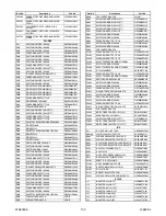


15-1
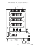
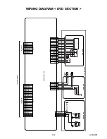
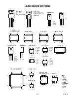
L2652CEX
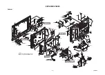
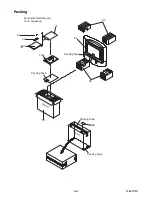
EXPLODED VIEWS
Cabinet
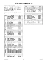
A9-1
A9-4
A9-4
A9-7
A9-3
A9-5
A9-5
A9-5
A9-6
A9
A9-2
L13
L13
1B1
DVD Main CBA Unit
L13
CL1701
CL1651
CL1207
CL1206
CL1205
LCD1
L3-10
B5
A1
B18
A18
A3
B30
L1
L14
L14
L14
L14
L14
L16
L16
L14
L29
L9
L14
L14
L14
B50
L9
L9
L23
L9
L9
L9
L9
L27
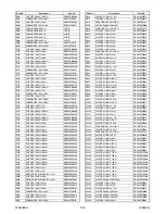
A6
S5
A10
B14
B7
B22
B3
B21
B45
A4
B14
B14
B27
B28
B31
B32
A15
See Electrical Parts List
for parts with this mark.
B22
Function CBA
Inverter CBA
L9
B34
A16
B18
L25
L22
L22
L22
A7
L4
L4
B4
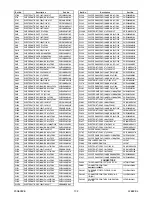
IR Sensor CBA
CLN801
SP802
SP801
Main CBA
AC601
B18
B54
B5
B5
B5
B5
B54
B18
B18
B21
B29
B21
B21
L9
CLN320
CLN802
Summary of Contents for EWL20D6
Page 17: ...5 3 L2652DC 1 Rear Cabinet S 2 S 1 S 1 S 3 S 1 S 1 Fig D1 2 Tilt Stand Assembly ...
Page 19: ...5 5 L2652DC 7 Main CBA 8 Inverter CBA S 9 S 9 S 9 S 9 S 10 S 10 Fig D3 ...
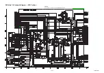
Page 40: ...10 3 Main 1 6 Schematic Diagram LCD TV Section L2652SCM1 ...
Page 41: ...10 4 L2652SCM2 Main 2 6 Schematic Diagram LCD TV Section ...
Page 42: ...10 5 Main 3 6 Schematic Diagram LCD TV Section L2652SCM3 ...
Page 43: ...10 6 L2652SCM4 Main 4 6 Schematic Diagram LCD TV Section ...
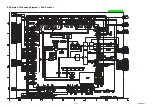
Page 45: ...10 8 L2652SCM6 Main 6 6 Schematic Diagram LCD TV Section ...
Page 46: ...10 9 L2652SCF Function Schematic Diagram LCD TV Section ...
Page 47: ...10 10 L2652SCIR IR Sensor Schematic Diagram LCD TV Section ...
Page 48: ...10 11 L2652SCI Inverter Schematic Diagram LCD TV Section ...
Page 50: ...10 13 L2652SCD2 DVD Main 2 3 Schematic Diagram DVD Section ...
Page 51: ...10 14 L2652SCD3 DVD Main 3 3 Schematic Diagram DVD Section ...
Page 55: ...10 18 Inverter CBA Top View BL2500F01021 Inverter CBA Bottom View ...
Page 74: ...EWL20D6 L2652UC 2006 06 26 ...