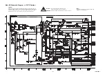
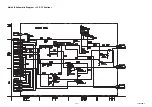
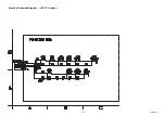
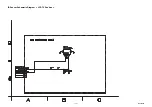

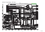
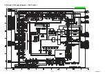


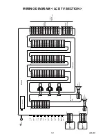


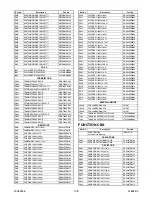


WIRING DIAGRAM < LCD TV SECTION >
L2652WI
12-1
LCD MODULE
TU1 TUNER UNIT
VIDEO
-Y IN
AUDIO(R)
-IN1
AUDIO(L)
-IN 2
S-VIDEO
IN
VIDEO
-Pb/Cb IN
VIDEO
-Pr/Cr IN
VIDEO1
-IN
AUDIO(L)
-IN1
AUDIO(R)
-IN 2
IR SENSOR
CB
A
MAIN CB
A
CLN904
FUNCTION
CB
A
CLN105
5
NU
1
3
4
2
5
1
3
4
2
CN1202
REMO
TE
AL+3.3V(D)
GND
P-ON-H
INVER
TER
CB
A
BA
CK
LIGHT
CN301
2
1
BA
CK
LIGHT
CN302
2
1
BA
CK
LIGHT
CN303
2
1
CN1207
1
3
2
5
4
7
6
8
9
10
13
12
11
14
15
17
16
19
18
21
20
22
23
24
27
26
25
28
VREF(4)
VREF(3)
VREF(2)
VREF(1)
VREF(0)
NU
P
ANEL+10.8V
P
ANEL+10.8V
NU
XA0
P
ANEL+3.3V
VREF(5)
VREF(6)
VREF(7)
VREF(8)
VREF(9)
NU
VCOM
VCOM
NU
P
ANEL-6V
NU
P
ANEL+3.3V
P
ANEL+3.3V
GND
P
ANEL+25V
NU
GND
CN1205
1
3
2
5
4
7
6
8
9
10
13
12
11
14
15
17
16
19
18
21
20
22
23
24
27
26
25
28
EB(3)
EB(4)
EB(5)
GND
CLKV
STV1
OFFEV
GND
GND
GND
GND
EB(2)
EB(1)
EB(0)
GND
EG(5)
EG(4)
EG(3)
EG(2)
EG(1)
EG(0)
GND
ER(5)
ER(4)
ER(3)
ER(2)
ER(1)
ER(0)
CN404
CN304
1
3
2
5
4
7
6
8
9
10
13
12
11
14
GND
GND
+22V
+22V
+22V
+22V
+22V
+22V
PR
O
TECT
-1
SP-L
SP-GND
GND
GND
GND
GND
CN1206
1
3
2
5
4
7
6
8
9
10
13
12
11
14
15
17
16
19
18
21
20
22
23
24
27
26
25
28
GND
OB(0)
OB(1)
OB(2)
OB(3)
OB(4)
OB(5)
GND
ODDINV
CLKH
EVENINV
OG(5)
OG(4)
OG(3)
OG(2)
15
1
3
2
5
4
7
6
8
9
10
13
12
11
14
15
OG(1)
OG(0)
GND
OR(5)
OR(4)
OR(3)
OR(2)
OR(1)
OR(0)
GND
STH1
POL
LP
CLN801
1
CN801
2
SP-R
SP-GND
CLN802
1
CN310
2
SP-L
SP-GND
A
C601
AC CORD
CN1201
1
3
2
4
1
3
2
4
KEY
-IN-2
AL+3.3V(D)
KEY
-IN-1
GND
CL1206
CL1205
CL1207
SP802
SPEAKER
L-CH
SP801
SPEAKER
R-CH
DIGITAL
AUDIO OUT
(COAXIAL)
1
5
3
9
7
CN1701
2
4
6
8
D
VD-C
D
VD-A
UDIO(R)
A
UDIO-GND
SPDIF
D
VD-MUTE
GND
GND
D
VD-A
UDIO(L)
D
VD-Y
1
5
3
9
7
CN1651
2
4
6
8
10
14
12
18
16
11
13
15
17
DISC-OUT
EV+3.3V
D
VD-ON+5V
EV+3.3V
D
VD-ON+3.3V
EV+9V
19
23
21
20
22
EV+3.3V
LED-CONT
EV+1.2V
EV+1.2V
EV+3.3V
D
VD-CS
PWRCON
D
VD-SCLK
GND
GND
EV+9V
GND
GND
GND
GND
GND
DISC-IN
25
24
D
VD-REMO
TE
D
VD-SD
A
T
A
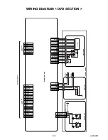
TO WIRING
DIAGRAM
<DVD SECTION>
TO DVD
MAIN CBA
UNIT CN601
TO DVD
MAIN CBA
UNIT CN401
Summary of Contents for EWL20D6
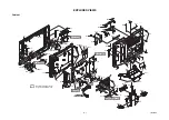
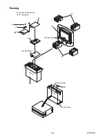
Page 17: ...5 3 L2652DC 1 Rear Cabinet S 2 S 1 S 1 S 3 S 1 S 1 Fig D1 2 Tilt Stand Assembly ...
Page 19: ...5 5 L2652DC 7 Main CBA 8 Inverter CBA S 9 S 9 S 9 S 9 S 10 S 10 Fig D3 ...
Page 40: ...10 3 Main 1 6 Schematic Diagram LCD TV Section L2652SCM1 ...
Page 41: ...10 4 L2652SCM2 Main 2 6 Schematic Diagram LCD TV Section ...
Page 42: ...10 5 Main 3 6 Schematic Diagram LCD TV Section L2652SCM3 ...
Page 43: ...10 6 L2652SCM4 Main 4 6 Schematic Diagram LCD TV Section ...
Page 45: ...10 8 L2652SCM6 Main 6 6 Schematic Diagram LCD TV Section ...
Page 46: ...10 9 L2652SCF Function Schematic Diagram LCD TV Section ...
Page 47: ...10 10 L2652SCIR IR Sensor Schematic Diagram LCD TV Section ...
Page 48: ...10 11 L2652SCI Inverter Schematic Diagram LCD TV Section ...
Page 50: ...10 13 L2652SCD2 DVD Main 2 3 Schematic Diagram DVD Section ...
Page 51: ...10 14 L2652SCD3 DVD Main 3 3 Schematic Diagram DVD Section ...
Page 55: ...10 18 Inverter CBA Top View BL2500F01021 Inverter CBA Bottom View ...
Page 74: ...EWL20D6 L2652UC 2006 06 26 ...


