9
15-1000 (1�03-68�9)
40
0�6
0�017
20
0�30
0�0085
1500 (103�4)
60
0�9
0�026
30
0�45
0�0130
2000 (137�9)
80
1�2
0�034
40
0�60
0�0170
2500 (172�4)
100
1�5
0�043
50
0�75
0�0210
3000 (206�8)
100
1�5
0�043
60
0�90
0�0260
4000 (275�8)
100
1�5
0�043
80
1�20
0�0340
5000 (344�8)
100
1�5
0�043
100
1�50
0�0430
6000 (413�7)
100
1�5
0�043
100
1�50
0�0430
Table 6 - Maximum seat leakage rate - Metal seated pressure relief valves
set pressure psig
(barg)
effective orifice sizes 0.307 in
2
and smaller d, e and f
effective orifice sizes larger than 0.307 in
2
g orifice and lager
Max. bubbles
per minute
approximate leakage rate per 24 hours
Max. bubbles
per minute
approximate leakage rate per 24 hours
standard cubic feet
standard cubic meters
standard cubic feet
standard cubic meters
Crosby
STylE JOS-E, JBS-E, JlT*-JBS-E, JlT*-JOS-E ValVES
InstallatIon and MaIntenance InstructIons
5.11 seat leakage tests
ambiguous terms such as 'bubble-tight',
'drop tight', 'zero leakage' and 'commercial
tightness' sometimes are used to describe seat
tightness� However, these terms lack uniform
definition and true practical meaning�
• Test procedure
aPI standard 527 provides a standard for
'commercial' tightness and has been adopted
by industry and users in order to clarify
testing methods and tightness criteria� This
standard applies to flanged inlet nozzle type
pressure relief valves�
• Test apparatus
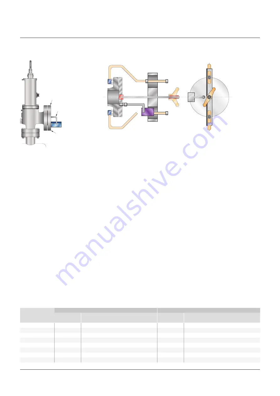
a typical test arrangement for determining
seat tightness for pressure relief valves
per aPI standard 527 is shown in Figure 4�
leakage is measured using a
5
/
16
inch OD
tube with 0�035 inch wall� The tube end is cut
square and smooth, is parallel to and ½ inch
below the surface of the water� a snap-on
type test clamp shown in Figure 5 is available�
• Procedure
With the valve mounted vertically, the
leakage rate in bubbles per minute shall be
determined with pressure at the pressure
relief valve inlet raised up to and held at
90 percent of the set pressure (or cold
differential test pressure - CDTP) immediately
after popping� This applies except for valves
set at 50 psig or below, in which case the
pressure shall be held at 5 psig below the set
pressure immediately after popping� The test
pressure shall be applied for a minimum of
one minute for valves of inlet sizes through 2”;
two minutes for sizes 2½”, 3” and 4”; five
minutes for sizes 6” and 8”� air (or nitrogen) at
approximately ambient temperature shall be
used as the pressure medium�
• Tightness standard
Metal-to-metal seated valves
The leakage rate in bubbles per minute shall
be observed for at least one minute and shall
not exceed the values indicated in Table 6�
noTe
The cover plate should be
fitted with a suitable device to
relieve body pressure in case of
accidental popping of valve
noTe
The tube must be bent so that reservoir runs
parallel to face of coverplate
FIguRE 4
Typical test arrangement
FIguRE 5
Seat leak apparatus for 150 and 300 lb� outlets 1” to 10” sizes
air receiver
Cover plate
Tube
5
/
16
” O�D� x 0�035” wall
[7�9 mm O�D� x 0�89 mm wall]
soft seated valves
For soft seated valves there shall be no
leakage for one minute (zero bubbles for one
minute)�
• Crosby seat tightness standard-liquid service
valves (Style JlT-E)
Crosby liquid service pressure relief
valves are checked for seat tightness by a
quantitative seat leakage test�


