The Analog Outputs
I/O Board Input and Output Setup • 17
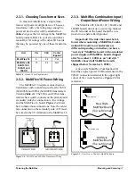
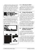
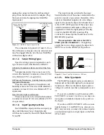
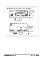
position of the
fail-safe switch
.
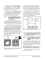
The fail-safe
switches for the outputs are on a switch bank at
the bottom right corner the plug-in output mod-
ule. Each switch corresponds to an output on the
board (switch #1 = output #1, etc.).
safe switch and Form C contacts should be con-
figured based on how you want the output to
perform during both normal operation and dur-
ing network/power loss.
Note: There are not many cases where you
would want a relay to be OPEN when called to
be ON. For most applications, you will want to
set the fail-safe switch to UP so that an ON com-
mand from the controller will close the relay.
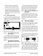
4.2.2. Relay Output Ratings and Fuse
Protection
Each relay output on the MultiFlex Combi-
nation I/O boards is rated for up to 240 VAC
with a maximum current of 2 amps.
Each relay is fused with a 2A fast-blow 5mm
x 20mm fuse, Bussman GMA-2 or equivalent.
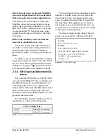
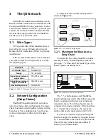
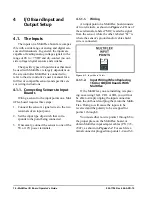
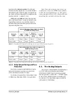
4.3. The Analog Outputs
All varieties of the MultiFlex board that have
an “AO” at the end of their model number
(88AO and 168AO) have four analog outputs
that can provide a variable 0V - +10VDC signal
to any of four variable-speed or variable-posi-
tion devices. The maximum output current for
each point is 10 milliamps.
State of Normally Closed (N.C.) Contacts
on MultiFlex Relay Points
Fail-safe
Switch
Light
is ON
Light
is OFF
Loss of
Communi
cation
Loss of
Power
Up (ON)
Closed
Open
Closed
Closed
Down (OFF)
Open
Closed
Closed
Closed
Table 4-1 - Output Board Fail-Safe and Switch Settings when Contact is Wired Normally Closed (N.C.)
State of Normally Open (N.O.) Contacts on
MultiFlex Relay Points
Fail-safe
Switch
Light
is ON
Light
is OFF
Loss of
Communi
cation
Loss of
Power
Up (ON)
Open
Closed
Open
Open
Down (OFF)
Closed
Open
Open
Open
Table 4-2 - Output Board Fail-Safe and Switch Settings when Contact is Wired Normally Closed (N.O.)
Summary of Contents for 810-3013
Page 1: ...026 1704 Rev 6 06 APR 10 MultiFlex I O Board Installation and Operation Manual ...
Page 2: ......
Page 4: ......

