background image

16 • MultiFlex I/O Board Operator’s Guide

026-1704 Rev 6 06-APR-10

1. Connect the input to the point labeled 

INPUT #1. This is the only point on the 
board that may accept this type of input.

2. Locate switch #8 on the dip switch bank 

labeled S3 (the same one that sets input 
board network ID). Set switch #8 to the UP 
(ON) position. This will tell the REFLECS 
that the input on point #1 is a pulse accumu-
lation input.

4.1.2. Power Connection

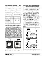
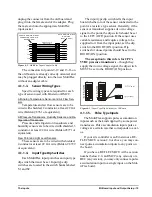
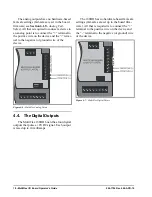
If power is needed to operate the sensor, four 

points are provided on the MultiFlex board that 
supply DC power: one +12VDC point, and three 
+5VDC points. See 

Figure 4-4

 for the location 

of these points.

4.1.2.1.

Current Ratings for On-Board 

Power Sources

The maximum current that may be drawn 

from the +12VDC terminal is 100 milliamps. 
The maximum current that can be drawn from 
all three +5VDC terminals COMBINED is 50 
milliamps.

4.1.2.2.

Powering Sensors Requiring 

24VAC Off the Power Transform-

er

Some sensors that requires 24VAC can be 

powered off the MultiFlex’s own 24VAC power 
connection. To connect to the 24VAC power 
source, connect the sensor’s power wires to ter-
minals AC1 and AC2. 

This can only be done with sensors that keep 

the 24VAC signal isolated from its DC output 
signal (such as CPC’s Dew Point Probe). If the 
output signal is not isolated from the 24VAC 
input, you must use a separate transformer.

4.1.3. Sensor Types for MultiFlex In-

put Points

Because different controllers may be com-

patible with different sensor types, this manual 
cannot list all sensor types and how to wire them 
to a MultiFlex input point. Refer to your site 
controller’s documentation for sensor wiring 
information.

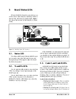
4.2. The Relay Outputs

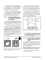
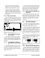
The MultiFlex Combination I/O boards have 

Form C relay contacts. 

Figure 4-5

 shows how to 

wire the three-terminal Form C contact.

One wire of the two-wire connection should 

always be connected to the middle terminal. The 
second wire must either be connected to the N.C. 
terminal (if you want the path to be closed when 
the relay is de-energized) or the N.O. terminal (if 
you want the path to be open during power fail-
ure).

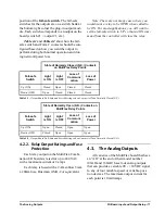
The contacts you choose also affect what the 

board’s fail-safe dip switch will need to be set to 
for proper operation. Refer to 

Table 4-1

 and 

Table 4-2

 on page 17. 

4.2.1. Output Fail-Safe Dip Switches

When a controller calls for a MultiFlex relay 

output to be ON, it sends a command to the Mul-
tiFlex to turn the output to the ON state (signi-
fied by the output LED being ON). The behavior 
of the relay when it is ON is determined by the 

Figure 4-4 - Input Board Power Sources

+5 VDC

+12 VDC

Figure 4-5 - Form C Contact Wiring

N.C.       N.O.

N.C.       N.O.

RELAY IS

CLOSED

ON POWER

FAILURE

RELAY IS

OPEN ON

 POWER
FAILURE

Summary of Contents for 810-3013

Page 1: ...026 1704 Rev 6 06 APR 10 MultiFlex I O Board Installation and Operation Manual ...

Page 2: ......

Page 3: ...n in this manual even if advised of the possibility of such damages In the interest of continued product development Computer Process Controls Inc reserves the right to make improvements to this manual and the products described herein at any time without notice or obligation READ ALL INSTRUCTIONS CAREFULLY If the equipment is not used in the manner specified by the manufacturer the protection pro...

Page 4: ......
Page 5: ...0 3 1 WIRE TYPES 10 3 2 NETWORK CONFIGURATION DAISY CHAINS 10 3 2 1 Maximum of Boards on a Daisy Chain 10 3 3 NETWORK ID NUMBERS 11 3 3 1 Numbering the MultiFlex 16 11 3 3 2 Numbering for MultiFlex Combination I O Boards 11 3 3 3 Addressing the 168DO 12 3 4 SETTING THE BAUD RATE 12 3 5 SETTING THE TERMINATING RESISTANCE JUMPERS 12 4 I O BOARD INPUT AND OUTPUT SETUP 14 4 1 THE INPUTS 14 4 1 1 Conne...

Page 6: ...Navigation 21 6 1 2 Opening Screen 22 6 1 3 Board Address 23 6 1 4 Settings 23 6 1 5 Input Output Select Menu 23 6 1 6 Input Screens 24 6 1 6 1 Input Status Config Menu 24 6 1 6 2 Status Volts 24 6 1 6 3 Status Eng Units 24 6 1 6 4 Input Config 24 6 1 7 Relay Output Screens 25 6 1 8 Analog Output Screens 26 6 1 8 1 Analog Status Override 26 6 1 9 Analog Fail Safes 27 6 1 10 Digital Status PWM 27 6...

Page 7: ... 16 communi cates with the site controller via an RS485 con nection to a REFLECS COM A D network or an Einstein I O network Dip switches on the board set the network ID board number and baud rate The board also provides both 5VDC and 12VDC output voltage points for use in power ing transducers or other input devices that require power Unlike the 16AI the MultiFlex 16 has a hand held terminal inter...

Page 8: ...ut boards also support a hand held terminal inter face which allows technicians to view input val ues check output states and override output points with fixed digital or analog values Table 1 2 shows the available models of MultiFlex combination input output boards Figure 1 2 MultiFlex 16AO Combination Input Output Board Figure 1 3 MultiFlex 1616 Combination Input Output Board 1 2 3 4 5 6 7 8 LEG...

Page 9: ...Einstein BX or BCU to control the store envi ronment in zones and pass along logging and alarm information The MultiFlex RTU has its own installation and operation manual P N 026 1706 1 3 2 The MultiFlex RCB The RCB is an improved version of the Mul tiFlex RTU The RCB has sixteen fully configu rable analog and digital input points whereas the RTU has only eight inputs two of which are configurable...

Page 10: ...n and operation manual P N 026 1705 1 3 4 The MultiFlex PAK The PAK is a distributed pack rack control ler that controls compressors and condenser fans The PAK can control up to 8 compressor groups containing up to 16 compressors The compressor control strategy is either Fixed Steps with up to 20 fixed combinations of compressor groups or an alternate Cyclic strategy that dis tributes compressor a...

Page 11: ...e boards be located adjacent to the Einstein I O boards may be mounted with out an enclosure but they should be mounted in a location that is not easily accessible to avoid tampering or damage 2 1 Snap Track Installation MultiFlex boards not supplied in a custom panel or other enclosure are supplied with a snap track for easy installation The insulation sheet and I O board must be removed from the...

Page 12: ...tween the base board and the panel door 2 3 Powering the MultiFlex All models of MultiFlex require a 24VAC Class 2 input power source The MultiFlex 16 requires the power source to be center tapped All other models do not use the center tap CPC supplies a wide variety of 24VAC trans formers with varying sizes and either with or without center taps Table 2 1 shows the trans former sizes and whether ...

Page 13: ...ultiFlex 16 2 3 3 MultiFlex Combination Input Output Board Power Wiring The MultiFlex 88 88AO 168 168AO and 168DO boards do not use a center tap Instead the 0V terminal on the board should be con nected to a separate Earth ground Important The rules that must be fol lowed when connecting a MultiFlex Combi nation I O board to a transformer are different depending on whether you have a new style Mul...

Page 14: ... tap boards on the net work will be damaged Figure 2 6 shows how to wire a non center tapped device to a center tapped transformer In addition the MultiFlex combination boards can be powered by one of the 50VA or 75VA non center tapped transformers listed in Table 2 1 on page 6 Figure 2 7 shows how to wire the transformers to the MultiFlex boards You may also tie one side of the secondary but not ...

Page 15: ...g I O boards use only the listed wire types from Table 2 3 Three conductor non shielded cables are the recommended wire for connecting between the center tapped trans former and the I O boards Shielded cable should not be used for power wiring The center tap should be wired with the third conductor to earth ground at the transformer Each MultiFlex board should have its 0V ter minal taken to a shor...

Page 16: ...hain A diagram of this network arrangement is shown in Figure 3 1 3 2 1 Maximum of Boards on a Daisy Chain To determine how many MultiFlex control lers may be daisy chained together look for a plus sign at the end of the model type on the board s plastic insulating cover The which appears on all MultiFlex boards manufactured after May 2004 means the board is equipped with a low power network trans...

Page 17: ...lex boards contains the same amount of relays as two 8RO boards these boards must be config ured as two 8RO boards with consecutive num bers Selecting an address on the output switch will number the relay outputs as an 8RO with the selected address and a second 8RO of the next consecutive address for example setting the switch to 1 will number the relays as 8RO 1 and 2 Figure 3 3 16 Network ID and...

Page 18: ...ey communicate Currently the baud rate dip switch in network components may be set at either 9600 or 19200 baud Either may be used refer to your site controller s user manual for the baud rate recom mendation currently 9600 baud for both REFLECS and Einstein controllers On all MultiFlex boards switches 6 and 7 on S3 are used to set the baud rate To communicate at 9600 baud set switch 6 UP and 7 DO...

Page 19: ...center of the board position Figure 3 6 shows the termination jumper set tings for all MultiFlex boards Figure 3 6 I O Network Termination Jumper Settings S4 S3 S2 S1 2 3 4 5 6 7 8 1 ON 2 3 4 5 6 7 8 1 ON 2 3 4 5 6 7 8 1 ON 2 3 4 5 6 7 8 1 ON TERMINATION JUMPERS NO TERMINATION IN toward center TERMINATION OUT toward left edge ...

Page 20: ... point 2 Set the input type dip switch that corre sponds to the point being connected 3 If necessary connect the sensor to one of the 5V or 12V power terminals 4 1 1 1 Wiring An input point on a MultiFlex board consists of two terminals as shown in Figure 4 1 One of these terminals labeled SIG reads the signal from the sensor while the other labeled 0v is where the sensor s ground and or cable shi...

Page 21: ...board whether or not the sensor connected to the point is a resistive type sensor Generally if the sensor or transducer supplies its own voltage signal to the point the dip switch should be set to the LEFT OFF position If the sensor uses variable resistance and requires voltage to be supplied to it from the input point set the dip switch to the RIGHT ON position Dip switches for unused points shou...

Page 22: ...int Probe If the output signal is not isolated from the 24VAC input you must use a separate transformer 4 1 3 Sensor Types for MultiFlex In put Points Because different controllers may be com patible with different sensor types this manual cannot list all sensor types and how to wire them to a MultiFlex input point Refer to your site controller s documentation for sensor wiring information 4 2 The...

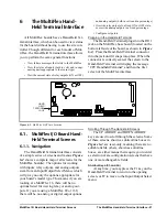
Page 23: ... with a maximum current of 2 amps Each relay is fused with a 2A fast blow 5mm x 20mm fuse Bussman GMA 2 or equivalent 4 3 The Analog Outputs All varieties of the MultiFlex board that have an AO at the end of their model number 88AO and 168AO have four analog outputs that can provide a variable 0V 10VDC signal to any of four variable speed or variable posi tion devices The maximum output current fo...

Page 24: ...e and the termi nal to the negative or ground wire of the device 4 4 The Digital Outputs The MultiFlex 168DO board has four digital outputs that pulse a 8VDC signal Each output is rated up to 10 milliamps The 168DO has no hardware based fail safe settings fail safes are set up in the board firm ware All that is required is to connect the terminal to the positive wire on the device and the terminal...

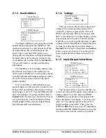
Page 25: ...eceives a message If the MultiFlex is connected to the network and set up to communicate with the controller you should see these lights blinking regularly If they do not there may be a problem with the net work 5 3 Code A and Code B LEDs All MultiFlex I O boards except the Multi Flex 16 have two LEDs labeled Code A and Code B These LEDs indicate failure conditions When these LEDs are OFF there ar...

Page 26: ...ified input type settings and analog output fail safes If Code B blinks at this rate on an opera tional board it means the board must be repro grammed This light does not blink if the board is new or is us ing the unmodified default configuration 5 4 Relay Output LEDs Each relay output point on a MultiFlex has an indicator LED that shows the status of the output This LED is lit to show the output ...

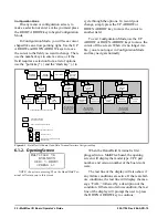
Page 27: ...ll display the message CPC Handheld Terminal and then the first screen of the MultiFlex interface 6 1 MultiFlex I O Board Hand Held Terminal Screens 6 1 1 Navigation The Hand Held Terminal interface consists of a simple series of screens and menus Figure 6 2 shows a complete map of all screens for the MultiFlex board s The options for working with inputs relay outputs and analog outputs stem from ...

Page 28: ...ng screen will display the model type CPC part number and version number of the board soft ware The last line of the display will also show if any failure conditions are active If there are fail ure conditions the last line will display the mes sage FAIL followed by a description of the condition If there is no failure condition the last line of the display will prompt the user to press the DOWN A...

Page 29: ... update within a few seconds and show the 8RO and 4AO board numbers 6 1 4 Settings This screen shows the baud rate dip switch setting for the board and the position of S3 switch 8 which is required to be UP for all RMCC all versions BEC all versions and BCU versions below 2 0 units if pulse accumu lation inputs are being used This screen does NOT allow you to change the baud rate or pulse settings...

Page 30: ...lts screen except it displays it in the engineering units designated for that input see Section 6 1 6 4 for more on how to set the engineering units The engineer ing unit chosen for the input is displayed in the right hand column The Hand Held Terminal shows four inputs at a time To view more inputs press the DOWN ARROW key to scroll down 6 1 6 4 Input Config The Input Config screen is where you s...

Page 31: ...sducer PSI ECLP500 KPA 5V 500 PSI pressure transducer KPA HUMIDITY RH Humidity sensor RH POWER KW Power transducer with 1 5V output NOT pulse count output KW REF LEAK Refrigerant Leak Transducer PPM DEW PT DF Dewpoint Probe DF F DEW PT DC Dewpoint Probe DC C LM235 DF LM235 Temperature Sensor DF F LM235 DC LM235 Temperature Sensor DC C Table 6 1 Engineering Units for MultiFlex Inputs REF LEVEL Refr...

Page 32: ...e any analog output to any voltage between 0 and 10 volts using the Hand Held Terminal interface To begin an override press the RIGHT ARROW key to enter Configuration Mode and use the DOWN ARROW key to move the cursor to the output you wish to override Use the number keys to enter the voltage value you wish to override the output to The number you enter may have up to one decimal place When you ha...

Page 33: ...ress the RIGHT ARROW key to make the cursor appear and use the DOWN ARROW keys to select the point you wish to override Enter a number from 0 to 100 that you wish to override the point to and press the UP or DOWN ARROW key to save changes and move the cur sor When pulsing during an override the 168DO will use the pulse period at which the output was pulsing before the override began If the output ...

Page 34: ...line it will immediately switch to its fail safe per centage and will remain at this rate until the board returns to on line status The 168DO will use the same pulse period it used before the board went off line If a digital output is not being commanded by any applications in the site controller it will pulse at the value programmed in its Config Fail field regardless of whether or not the board ...

Page 35: ... 8 located on the output board layer of MultiFlex I O boards and next to switch bank S1 on the 8ROSMT can be used to change the state of the relays A fail safe switch in the ON position will cause the corresponding relay to be energized i e OPEN on the N C terminals and CLOSED on the N O terminals A fail safe switch in the OFF position will cause the relay to be de ener gized i e CLOSED on the N C...

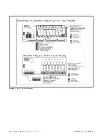
Page 36: ...30 MultiFlex I O Board Operator s Guide 026 1704 Rev 6 06 APR 10 Figure 7 1 Relay Output Test Modes ...

Reviews: