background image

6      Chapter 2  Installation 

RDU-S Rack Data Unit    User Manual 

2.3   Installing Data Unit 

The data unit can be installed in a standard 19

 rack through hangers (accessories) or a round hanger (accessory). It 

can also be mounted on the wall through hangers. 

2.3.1   Installation Hole Position 

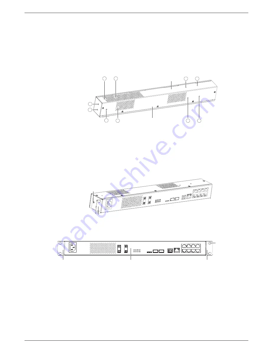
The hangers are installed on the side panels and the round hanger is installed on the back panel or top panel. The 

installation holes on the panels are shown in Figure 2-1. 

1

2

3

5

6

4

7

8

9

10

Top panel

Back panel

Left panel


Figure 2-1    Positions of installation holes 

The installation holes 

ķ

 and 

ĸ

  (also two installation holes on the right panel) are used for installing the hangers 

and the installation holes 

Ĺ

 ~ 

ŀ

  are used for installing the round hanger. 

2.3.2   Installing The Data Unit In A Standard 19

 Rack 

Installing the data unit through hangers 

1. Fasten two hangers respectively to both sides of the data unit with M3 screws, as shown in Figure 2-2. 

ᆹ㻵ᆄ

ᤲ㙣

Installation hole

Hanger


Figure 2-2    Installing hangers (rack mounting) 

The completed status is shown in Figure 2-3. 

Hanger

Hanger

Processing unit

Fixing hole
(4 pcs)


Figure 2-3    Completed status figure 

2. Put the data unit onto the guide rails in the rack and push it into the rack completely.   

3. Wrench M6 screws into the fixing holes (see Figure 2-3) of the hangers to fasten the data unit onto the rack. 

Summary of Contents for RDU-S

Page 1: ...e nearest Emerson local sales office or service center Copyright 2010 by Emerson Network Power Co Ltd All rights reserved The contents in this document are subject to change without notice Emerson Network Power Co Ltd Address No 1 Kefa Rd Science Industry Park Nanshan District 518057 Shenzhen China Homepage www emersonnetworkpower com cn E mail support emersonnetwork com cn ...

Page 2: ......

Page 3: ...2 Installing The Data Unit In A Standard 19 Rack 6 2 3 3 Installing The Data Unit On The Wall 7 Chapter 3 Connection 8 3 1 Connection Notes 8 3 2 Connecting Sensor Ports 8 3 2 1 Connecting 1 Wire Sensor Port 8 3 2 2 Connecting DI1 DI2 And DI3 Ports 9 3 2 3 Connecting IRM Sensor Port 10 3 3 Connecting Serial Ports 11 3 4 Connecting Relay Ports 12 Chapter 4 Parameter Setting 13 4 1 Connecting Data U...

Page 4: ...ontrol Interface Operation Description 27 5 4 Configure Interface Operation Description 29 5 5 Events Interface Operation Description 39 5 6 History Interface Operation Description 41 5 7 System Information Interface Operation Description 43 5 8 Logout 43 Chapter 6 Troubleshooting 44 Appendix 1 Command Lines 45 1 Overview 45 2 Main Command Lines 45 ...

Page 5: ...als and non electric signals in real time The small profile design makes it suitable for installation in small space in the rack 1 1 1 Appearance The appearance of the data unit is shown in Figure 1 1 100 a Input DO2 12V GND DO1 12V GND USB USB Micro SD USB CONFIG ETH DI1 DI2 DI3 COM1 DO1 DO2 ALARM POWE R RUN 240V TH_BU S COM2 COM1 1 2 TH_BUS COM2 Figure 1 1 Appearance 1 1 2 Indicators The indicat...

Page 6: ... GND USB USB Micro SD USB CONFIG ETH DI1 DI2 DI3 COM1 DO1 DO2 ALARM POWE R RUN 240V TH_BU S COM2 COM1 1 2 TH_BUS COM2 DI1 port Amplified figure of RJ45 ports DI1 DI3 COM1 DI2 TH_BUS COM2 RJ45 ports Power input port 12Vdc power ground port Relay ports USB ports USB CONFIG port Ethernet port Micro SD card slot 12Vdc power output port DI2 port DI3 port 1 wire sensor port 1 wire sensor port Serial por...

Page 7: ... 5 NC GND NC GND GND 6 NC D2 NC RXD RXD 7 NC D3 D T D D 8 GND D4 D T D D 1 2 Technical Specifications 1 2 1 Input Specifications The input specifications of the data unit are listed in Table 1 4 Table 1 4 Input specifications Input parameters Corresponding port Measurement accuracy Descriptions 1 wire sensor input 1 wire signal 1 wire sensor port The final accuracy is determined by the used sensor...

Page 8: ... the temperature range 1 2 4 Mechanical Specifications The mechanical specifications of the data unit are listed in Table 1 7 Table 1 7 Mechanical specifications Dimensions L W H Weight 440mm 44 2mm 55mm 1 5kg 1 3 Options The options of the data unit are listed in Table 1 8 Table 1 8 Options Classification Optional model Digital sensors 1 ER ST01P infrared sensor RJ45 port 2 EE SD01S smoke sensor ...

Page 9: ...ature and humidity should meet the product specifications see Table 1 6 EMI For EMI purpose take the following measures z Do not connect the working ground of the data unit to ground of electrical power equipment or lightning ground Instead place them away from each other as far as possible z Keep the data unit away from large power radio transmitters radar transmitters and high frequency large cu...

Page 10: ...es ķ and ĸ also two installation holes on the right panel are used for installing the hangers and the installation holes Ĺ ŀ are used for installing the round hanger 2 3 2 Installing The Data Unit In A Standard 19 Rack Installing the data unit through hangers 1 Fasten two hangers respectively to both sides of the data unit with M3 screws as shown in Figure 2 2 ᆹ㻵ᆄ ᤲ㙣 Installation hole Hanger Figur...

Page 11: ...angers respectively to both sides of the data unit with M3 screws as shown in Figure 2 5 Note The installation direction of the hangers in wall mounting mode is opposite to that in rack mounting mode ᤲ㙣 ᆹ㻵ᆄ Hanger Installation hole Figure 2 5 Installing hanger wall mounting 2 Use a drill aiguille Φ6 to drill four holes depth 70mm on the wall according to the dimensions in Figure 2 6 and knock four...

Page 12: ...es six sensor ports silkscreen DI1 DI2 DI3 TH_BUS and to connect the sensors z The 1 wire sensor port silkscreen is supportive of 1 wire sensor z The DI1 DI2 and DI3 ports are supportive of digital sensors including infrared sensor water sensor door magnet sensor smoke sensor and so on z The IRM sensor port silkscreen TH_BUS is supportive of IRM series sensor including temperature sensor and tempe...

Page 13: ...I1 DI2 and DI3 ports Pin definition The pin definition of the DI1 DI2 and DI3 ports is shown in Figure 3 4 1234 5 678 2 NC 3 D1 smoke sensor 4 GND Pin definition 1 12Vdc 5 GND 6 D2 door magnet sensor 7 D3 water sensor 8 D4 infrared sensor Figure 3 4 Pin definition of DI1 DI2 and DI3 ports Connection method Note 1 It is recommended to use the auxiliary sensors shown in Figure 3 5 If you want to con...

Page 14: ...necting door magnet sensor Connecting infrared sensor Figure 3 6 Connecting multiple sensors When a port is connected with multiple signals simultaneously you must note that the line sequence conflict of the signals cannot occur For example the DI1 port can be connected with four sensors simultaneously The recommended sensors include smoke sensor door magnet sensor water sensor and infrared sensor...

Page 15: ... are used to connect Emerson serial PDU Port position The positions of the serial ports are shown in Figure 3 9 DO2 12V GND DO1 12V GND USB USB Micro SD USB CONFIG ETH DI1 DI2 DI3 COM1 DO1 DO2 ALARM POWE R RUN TH_BU S COM2 COM1 1 2 TH_BUS COM2 Serial ports 100 240V Input Figure 3 9 Positions of serial ports Pin definition The pin definitions of the serial ports are shown in Figure 3 10 12 345 67 8...

Page 16: ...al ports COM1 and or COM2 3 4 Connecting Relay Ports Port position The positions of the relay ports are shown in Figure 3 12 DO2 12V GND DO1 12V GND USB USB Micro SD USB CONFIG ETH DI1 DI2 DI3 COM1 DO1 DO2 ALARM POWER RUN TH_BU S COM2 COM1 1 2 TH_BUS COM2 Relay ports 100 240V Input Figure 3 12 Positions of relay ports Connection method When the relay output specification reaches 5A 24Vdc connect t...

Page 17: ...it connect the data unit with the computer using a standard network cable and set the communication parameters through the computer 4 2 Setting HyperTerminal This section takes Windows XP as an example to illustrate how to set HyperTerminal After the network cable is connected set the HyperTerminal according to the following procedures 1 Click Start Programs Accessories Communications HyperTermina...

Page 18: ...e device requirement 3 The HyperTerminal setting is completed Note Before powering on the device confirm the location of the power input port see Figure 1 3 to make sure that the power can be cut off in time in case of an accident 4 3 2 Checking After Powering On Insert the power cable to power on the data unit and check that 1 The indicators see Figure 1 2 of the data unit are working normally Se...

Page 19: ...name and the password are case sensitive 4 5 Setting IP Address After logging onto the command line use the command setip first to set the IP address of the data unit The detailed setting procedures are given as follows 1 Type setip following the command prompt RDU_admin and press the Enter key as shown in the following figure 2 Respectively type the new IP address sub_net mask and default gateway...

Page 20: ... system will retrieve the factory default IP address after 5 minutes 4 6 Restarting Data Unit Use the command reboot to restart the data unit after all parameters are set The detailed procedures are given as follows 1 Type reboot following the command prompt RDU_admin and press the Enter key as shown in the following figure 2 Type Y or N according to the system prompt Typing Y will restart the dat...

Page 21: ...ddress of the data unit in the address bar of Internet Explorer browser and press the Enter key to enter the login interface as shown in Figure 5 1 Figure 5 1 Login interface 2 Select the correct user name default admin from the User Name drop down list and type the correct password default emerson in Password and click Login to enter the software operation interface Note 1 Both the user name and ...

Page 22: ...g status of input contacts output relays and the last alarms through the Environmental tab z View and set the working status of the PDU through the PDU tab z View and set the working status of the cameras through the Camera tab 5 2 1 Environmental Click the Environmental tab in the operation area and the interface shown in Figure 5 2 will appear You can set the temperature sensors and humidity sen...

Page 23: ...ompt box displaying sensor name and sensor location will appear as shown in Figure 5 6 Figure 5 6 Prompt box Humidity sensor The operation of the humidity sensor is the same as that of the temperature sensor Input contacts Click the Input Contacts node in the Monitor structure tree and the figure shown in Figure 5 7 will appear You can view the working status of the connected digital sensors If th...

Page 24: ...lay the latest 20 events in the event list including High Critical Low Critical Critical High Warning Low Warning Loss of Comms and Normal events If you want to clear the Loss of Comms events in the event list click the Comms Loss Reset button in the SN DI Sensor Configure window shown in Figure 5 46 Figure 5 10 Event list 5 2 2 PDU Click the PDU tab in the operation area to enter the PDU interfac...

Page 25: ... The data unit supports three types of PDU metered PDU switched PDU and Mps PDU through RS485 serial protocol provided by Emerson Figure 5 12 PDU page Metered PDU For metered PDU click Signal tab and Event tab to check the status of PDU and abnormal events Click Control tab to set the address upper load current and lower load current of the PDU The tabs are shown in Figure 5 13 Signal tab Event ta...

Page 26: ... 13 Tabs of metered PDU In the Control tab click the icon in the Operation column to set the address or threshold for metered PDU as shown in Figure 5 14 Figure 5 14 PDU setting windows Switched PDU For switched PDU the PDU page is shown in Figure 5 15 Figure 5 15 PDU page switched PDU ...

Page 27: ...of the Switched PDU out port Control Click Turn On and Turn Off to control the On Off status of the Switched PDU output port Click More on the lower right corner to enter the detailed information window which also has three tabs Signal Event and Control as shown in Figure 5 16 Signal tab Event tab Control tab Figure 5 16 Detailed information window In the Control tab the setting method of switched...

Page 28: ...refer to PDU in 5 4 Configure Interface Operation Description for detailed method Mps PDU The Mps PDUs are divided into different models depending on the PDU length and whether each outlet can be controlled and the interface of each model differs The following takes one model as an example to introduce the interface of Mps PDU which contains three tabs Click Signal tab and Event tab to check the s...

Page 29: ...red PDU 5 2 3 Camera 1 Click the Camera tab in the operation area to enter the Camera interface as shown in Figure 5 18 Figure 5 18 Camera interface 2 Extend the USB Camera node Click All Camera and camera1 and camera2 images will be displayed simultaneously in the interface as shown in Figure 5 18 Click Camera1 or Camera2 and the corresponding camera image will be displayed in the interface ...

Page 30: ...ton will turn to Stop after the recording action is initiated and click the Stop button to stop recording as shown in Figure 5 19 Note If Rewriting is ticked when the SD card is full the foremost records will be covered by the newly taken pictures and videos Figure 5 19 Control buttons The capture picture list and the preview window are shown in Figure 5 20 and Figure 5 21 respectively Figure 5 20...

Page 31: ... video replay window Note 1 Do not pull out the SD card during recording 2 For alarm event the recording time is two minutes at most for manual recording the recording time is 15 minutes at most 5 3 Control Interface Operation Description Click the Control tab to enter the Control interface as shown in Figure 5 24 ...

Page 32: ...it will be restarted Digital output control 1 Click the Digital Output Control node in the Control interface and the figure shown in Figure 5 26 will appear Figure 5 26 Digital output control window Select the control mode including On and Off in DO1 Output and DO2 Output and click Apply Firmware update 1 Click the Firmware Update node in the Control interface to upgrade the firmware file of the d...

Page 33: ...w shown in Figure 5 28 will appear Figure 5 28 Configuration file window 2 Click Browse select the configuration file of the data unit in the pop up Select file dialogue box and click Upload to update the configuration file into the data unit Restore factory defaults Click the Restore Factory Defaults node in the Control interface to restore the system default setting and the window shown in Figur...

Page 34: ...IP address in five minutes the IP address will be restored as 192 168 0 10 2 The system obtains the IP address in five minutes and then the system will be restarted automatically Wait five minutes and then you can view the dynamic IP address in the Current_DHCP_IP txt file in the background computer that is connected to the data unit through the USB CONFIG port 2 Before using the DHCP service plea...

Page 35: ...ed the port number is 465 z If you have not modified the port number when you check or uncheck SSL the port number will be switched between 465 and 25 z If you have set other port number manually when you check or uncheck SSL the port number will always be the user defined value not being changed 1 SMTP server Click the SMTP Server tab and the window shown in Figure 5 32 will appear As shown in Fi...

Page 36: ...you an Email under any event generated by all sensors except the event generated by the third party intelligent devices for example PDU 3 Test Click the Test tab and the window shown in Figure 5 35 will appear Figure 5 35 Test window Click Test the data unit will send a test Email to the recipient address SMS Click the SMS node and the window shown in Figure 5 36 will appear You can set the SMS fu...

Page 37: ...ers window 2 Click Add Recipients and the window shown in Figure 5 38 will appear Figure 5 38 Adding phone number window 3 Type a new phone number in the textbox after Configure Phone and click Apply 4 Select a phone number and click Delete and the number will be deleted Note At most eight phone numbers can be added SNMP Click the SNMP node and the window shown in Figure 5 39 will appear Figure 5 ...

Page 38: ...ps for all events 3 Select SNMP V2c type a new NMS IP address in NMS IP and keep other parameters in default 4 Click Apply the setting is successful Click Cancel the setting is cancelled 5 Select SNMP V3 the window shown in Figure 5 41 will appear Figure 5 41 Select SNMP V3 6 Click Apply the setting is successful Click Cancel the setting is cancelled 2 Deleting NMS Select one NMS and click Delete ...

Page 39: ...getting local time and getting time through NTP server You can also set the calibration interval through the NTP server and select the Time Zone In addition you can disable and enable Daylight Saving Time DST by the following method z Select Disable to disable Daylight Saving Time z Select Automatically adjust clock for daylight saving time only when 5 00 8 00 is selected for Time Zone z Select Ma...

Page 40: ...Figure 5 45 will appear Figure 5 45 DI sensor configure window Note For third party equipment Custom must be selected in the Type column in the DI sensor configure window 2 Select the DI Sensor Configure tab and the window shown in Figure 5 45 will appear You can enable or disable the DI channels and set the DI type and name of the DI channels Click Apply to complete the configuration 3 Click the ...

Page 41: ...7 TH sensor configure window Note 1 At most ten SN TH temperature humidity sensors can be configured 2 The serial numbers of the sensors will be displayed in the Address column automatically 3 At most eight IRM series temperature sensors and eight IRM series temperature humidity sensors can be connected with the system After NForm is connected when IRM series sensors are used the system supports a...

Page 42: ...of the PDU for your reference 2 After finishing all actions such as adding modifying and deleting click Apply to enable all the settings and the system will be rebooted Auto logout Click the Auto Logout node and the window shown in Figure 5 50 will appear Type the time such as 15 the setting range is 0min 15min in Auto logout mins and click Apply You may set the value as 0 and the system will neve...

Page 43: ...ents interface as shown in Figure 5 52 Figure 5 52 Events interface Digital input actions Click the Digital Input Actions node and the figure shown in Figure 5 53 will appear You can configure the output mode of alarm events for the digital sensors through the interface When an alarm is generated you can select the alarm output mode according to the severity of the alarm event including EventLog E...

Page 44: ...stem can selectively output it according to the alarm class The output mode includes Email Email notification Camera USB video through USB Camera and DO audible and visual alarm through the relay Figure 5 54 Temp Hum action window Note Among the selections in the sensor whose name is SN Temp XX or SN Hum XX belongs to 1 wire mode the sensor whose name is SerialTXX or SerialHXX belongs to RS485 mod...

Page 45: ...re 5 57 Clear Event History window 2 Click Clear Event History and the historical events will be cleared 5 6 History Interface Operation Description Click the History tab to enter the History interface as shown in Figure 5 58 Chart Click the Chart node to enter the historical data interface in chart mode as shown in Figure 5 58 The chart of two sensors will be displayed by default After the sensor...

Page 46: ...face in chart mode Table 1 Getting historical data Click the Table node to enter the historical data interface in table mode as shown in Figure 5 59 You may click Time Name Value and Unit to list the data in the corresponding sequence respectively Figure 5 59 Historical data interface in table mode ...

Page 47: ... Figure 5 61 will appear Figure 5 61 Clear History Data window 2 Click Clear History Data and the historical data will be cleared 5 7 System Information Interface Operation Description Click the System Information tab to enter the System Information interface as shown in Figure 5 62 You can view the version information of the system and hardware through the interface You can also define the Site N...

Page 48: ...k that no obstructs exit in the Micro SD card slot 2 Check that the Micro SD card is inserted in place It is recommended to insert it again 3 Restart the data unit After unplugging and plugging the Micro SD card the data unit must be restarted to read the data No response occurs after the corresponding sensor is connected 1 Check that the sensor is working normally 2 Check that the configuration f...

Page 49: ...get online help information at any moment after logging z Provide the relative commissioning information help to diagnose network malfunction z Support key word input mode You only need to input part of the key word related to a command and the shell can recognize the command for example to run the command lookstatus just type look 2 Main Command Lines 1 or help Type or help under the command prom...

Page 50: ... through Ethernet port It is recommended to use a network that offers a high speed 3 After a file is downloaded upload the file to check if the download is successful 4 For upgrading the firmware successfully command 2 Delete all the files in RDU directory should be processed before command 1 Download firmware rdus files and decompress to RDU directory 3 Logout The logout command is used to exit t...

Page 51: ...l port test z Type 4 and press the Enter key stop serial port test z Type 5 or q and press the Enter key exit the test command and return to the main interface of command line If you do not have any operation for the command within five minutes the software will automatically exit and return to the main interface of command line 9 Show The show command is used to display the product information Ty...

Page 52: ...minutes the software will automatically exit and return to the main interface of command line Note 1 Upon the first startup of the system a static IP address is assigned to the system with DHCP disabled Once the DHCP is started a dynamic IP address is obtained each time the system starts You can disable DHCP with the command stopmod 2 If DHCP is enabled there are two conditions as follows 1 The sy...

Page 53: ...it the stopmod command and return to the main interface of command line 13 Setrtc The setrtc command is used to set the real time clock Type setrtc under the command prompt RDU_admin and press the Enter key as shown in the following figure 14 Version The version command is used to show the device version information including hardware version information and software version information Type versi...

Reviews: