3
6
10
operating properly and its frequency response is correct (Section 3.4a), allowing the unit to operate
with maximum efficiency.
1.
Place the transmitter in standby and connect the test equipment available for monitoring
intermodulation, sync amplitude and differential gain and phase.
2.
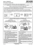
Remove the top cover of the Exciter drawer and insure that the Linearity Corrector
BYPASS/ENABLE switch (A2PC2S1) is in the ENABLE position causing the front panel
LINEARITY CORRECTOR light to illuminate.
3.
Place the transmitter in operation with the system providing its rated output power. After
demodulating video, find the distortion that needs the most correction and slowly adjust the
potentiometers shown on the table below dedicated to that type of distortion. Those
adjustments designated as CUT IN are used to position the correction on a specific part of
the waveform being modified. Those adjustments specified as SLOPE increase and
decrease the amount of correction applied. Remember that the corrector was factory
calibrated and should need very little readjustment. Also, be aware that, while manipulating
the corrector, the transmitter’s output must be carefully monitored since changes in linearity
can significantly alter the unit’s output power.
ADJUSTMENT
CORRECTION
FUNCTION
R21
Diff. Phase
Cut In
R15
Diff. Phase
Slope
R30
Diff. Phase
Cut In
R25
Diff. Phase
Slope
R47
Diff. Gain
Cut In
R41
Diff. Gain
Slope
R55
Sync
Cut In
R57
Sync
Slope
4.
After the adjustments in step #3 are completed, modulate the visual signal with a modulated
ramp waveform and place the transmitter signal on a spectrum analyzer (100kHz resolution
bandwidth) to view in-band intermodulation distortion. Carefully readjust R21 and R15 to
null the IM
3
distortion products.
5.
Check and, if necessary, readjust the transmitter's output power using the Exciter’s Control/
Interface AMPLIFIER GAIN ADJUST (A2PC4R7).
6.
Repeat steps #3 and #4 to find the appropriate trade-off between differential phase,
differential gain, sync amplitude and intermodulation distortion.
7.
Place the transmitter in standby, remove the test equipment, reinstall the top cover on the
Exciter and slide the drawer back into the cabinet. Properly load the transmitter’s output
and place it back on the air.