


7
NOTE
In case of priming difficulties: use a normal syringe to suck liquid from the discharge nipple while the
pump is in operation (air bleed valve closed), continuing until you actually see the liquid rise in the syringe. Use a
short piece of suction hose to connect the syringe to the discharge nipple (refer parag.”TROUBLESHOOTING”).
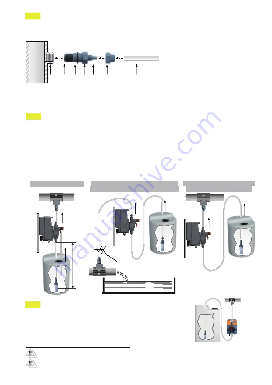
3.1 - INJECTION VALVE INSTALLATION DIAGRAM
e.
- Select the most appropriate injection point on the system pipe to be treated and fit a 3/8" female gas
threaded connection (BSPf): connection not supplied with the pump. Screw injection fitting into the
connection (fig.9). We recommend the use of a clamp-saddle for a clean installation.
- Although the injection fitting is provided with o-ring, we suggest increasing the sealing with PTFE tape.
- Connect discharge hose to the conical connector on the injection fitting and lock it with supplied hose-nut.
NOTE
The injection valve also acts as no-return valve by means of a cylinder sleeve (elastomer, standard
supplied in FPM “Viton”). Available also Hastelloy Spring return valve with ball checks. The “sleeve”
D
must not be removed, performances will drastically change especially when operating at atmospheric
working pressure: flow rates will increase beyond performance curves (page 6).
3.2 - DOSING PUMPS TYPICAL INSTALLATIONS DIAGRAMS
(fig.10, 11, 12)
- When operating at atmospheric pressure (no back-pressure) and additive chemical tank is located above
injection point (fig.11), injection valve condition should be checked at regular intervals because excessive
wear could cause additive to drip into the plant even when the pump is OFF. If the problem persists, install a
proper calibrated counter-pressure valve (C) between injection point and pump head discharge side.
- When dosing tank level and injection point are higher above the pump (fig.12), check hoses conditions.
- With chemicals generating vapours, don’t install the pump above the tank unless hermetically sealed.
NOTE
INSTALLATION NOTE FOR PVDF AUTOBLEED PUMP HEAD:
Auto-bleed pump head expels automatically air bubbles that are formed by the
chemical additive and are present into the suction tube thus during pump priming
there is no need for manual intervention. However, although this functions is
absolutely guaranteed, it’s always advisable to mount the pump with overflow
suction position (as shown in fig.13) just to prevent a sudden increase of air due to
mostly to temperature increase or when using a mixer.
4.0 – DISMANTLEMENT AND DISPOSAL
Commissioning, maintenance and repairs operations must be carried out by qualified personnel only
Operator must always protect itself when handling hazardous feed chemicals.
Fig.13
A
- Process plant
B
- 3/8" female steel gas thread connector
C
- Cylinder sleeve (no return valve)
D
- O-ring
E
- Injection fitting
F
- Conical fitting to connect discharge hose
G
- Hose tube nut
H
- Polyethylene discharge hose
A
B
C
D E F
G
H
Fig.9
Fig.10
TYPICAL INSTALLATION
delivery line
m
ax
2
m
INSTALLATION WITH INJECTION POINT
LOWER THEN PUMP AND DOSING TANK
Fig.11
counter-pressure valve
(recommended)
INSTALLATION WITH INJECTION
POINT HIGHER THEN DOSING
TANK
Fig.12


