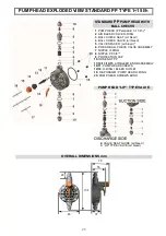
emaux CTRL2-5L Operatinginstructions And Maintenance Download Page 22


22

EXPLODED VIEWS  


SOLENOID EXPLODED VIEW  


A. PISTON  
B. THERMAL SENSOR ASSEMBLY  
C. SOLENOID COIL ASSEMBLY 
D. WIRES TO CIRCUIT 
E. NOISE REDUCTION WASHER 
F. MOVING PLATE 
G.


PRELOADING RING


H. FLAT SPRING


I.  WASHER 
J. NUT


NOTE


the above drawing shows the main components of a typical solenoid, however each type of performance  

            could have extra components to keep in mind when  contacting EMAUX customer service.


1. pump head (complete) 
2. diaphragm / pump head o-ring 
3. 
PTFE diaphragm 
4. 
piston flange 
5 / 9. 
power cable assembly 
6. 
front controls panel  
7. housing


8. controls PCB (printed circuit board) 


10. pcb internal mounting screws 
11. solenoid 
12. wall quick mounting bracket 
13 / 15. utility connector assembly 
14. back housing 
16. 
housing screws 

11 

12 

16 

14 

13 

10 

15 

A  

H

B  

To  test  solenoid  reliability, 
attach  tester  to  the  two  wires 
and check electrical resistance  
from “Troubleshooting” 
paragraph page 20 point 4. 

COMPLETE ASSEMBLED SOLENOID 

Summary of Contents for CTRL2-5L

Page 1: ...CTRL2 5L CTRL2 7L SERIES DUAL PARAMETER PH RX MICROCONTROLLER SOLENOID DRIVEN DOSING PUMP OPERATING INSTRUCTIONS AND MAINTENANCE EMPU12053149 ENGLISH...

Page 2: ...ARAMETERS AND FUNCTIONS LAYOUT pH default page 12 10 0 PROGRAMMING CONTROLLER 11 0 CALIBRATION page 13 15 12 0 PROGRAMMING SET POINT 13 0 SET POINT SETTINGS page 15 17 14 0 ALLARM SETTINGS 15 0 RESET...

Page 3: ...ger However save packaging it can be used for future shipments Before connecting the equipment ensure voltage ratings corresponds to local power supply You will find these characteristics in the produ...

Page 4: ...IALS PARTS IN CONTACT WITH LIQUID STANDARD VERSION UPON REQUEST Pump head PP PVDF PMMA MEMO1 NOTE AISI316 Diaphragm PTFE Ball check valve CERAMIC AISI 316 Pump head Nipples Hose nut PP PVDF AISI 316 S...

Page 5: ...nt side for sliding pump rear slots Mounting bracket side view Fig 3 Drill two holes and insert dibbles then screw in bracket Slide pump into slots Performance curves fig 2 are obtained testing the pu...

Page 6: ...7 always use curved joints with suction or discharge hose Try to keep both the suction and discharge hose as straight as possible avoiding all unnecessary bends always use our standard strainer foot v...

Page 7: ...e condition should be checked at regular intervals because excessive wear could cause additive to drip into the plant even when the pump is OFF If the problem persists install a proper calibrated coun...

Page 8: ...ls are pumped especially If a reduction of the required additive concentration in the process plant is detected this could be caused the reduction of the dosing pump flow rate by valves wearing in whi...

Page 9: ...ns CONNECTOR 1 CONNECTOR 1 Level switch connection fig 15 Configurations Pin 1 NO connection Pin 2 NO connection Pin 3 Level switch wire Pin 4 Level switch wire PUMP LOWER SIDE Power cable clamp pH or...

Page 10: ...al mode selection of proportional range value Delay adjustment Delay at powering ON electrodespolarization Stand by for cleaning electrodesand sensors or re calibration 7 3 LEVEL CONTROL ONLY CTRL2 L...

Page 11: ...quency based to maximum measuring value 9 0 PARAMETERS AND FUNCTIONS pH default DEFAULT Set point setting 7 2 Hysteresi s setting 0 1 Choice of intervention of dosing field acid alkaline Acid Selectio...

Page 12: ...ogramming moves to measuring mode display will show current measured value Press OK to enter menus it will show SETPOINT menu using or buttons to scroll all 4 menus Set point menu Calibration menu Ala...

Page 13: ...ature compensation that is setting the temperature at the same value of the system to be treated and such value will remain constant Also it s possible to switch from C celsius defau lt to F Fahrenhei...

Page 14: ...POINT 2 Dip RX electrode into buffer solution 475 or 250 or 650mV Using or adjust until display shows the buffer solution value Press OK to confirm BNC CONNECTOR 12 0 PROGRAMMING SET POINT NOTE To ha...

Page 15: ...ed by the user at max frequency chapter 11 5 and will stop once reached required set point PROP with this mode the pump will dose proportionally to the current measured value and its distance to selec...

Page 16: ...00 120 imp min STEP 3 With and select minimum measured value to correspond dosing pump minimum injection frequency Press OK to confirm and exit Set point menu Press ESC to return to measuring mode 15...

Page 17: ...are steps for RESET procedure Switch OFF and ON the unit Press at the same time ESC and OK until display will show the latest firmware revision e g 02 3 3 then will appear SET UP and default paramete...

Page 18: ...ion d Check system pressure cause 2 chemical can produce crystalline deposits in the hydraulic parts or clogging the filter 2 GREEN LED LIT AND RED LED FLASHING PUMP PULSES BUT PUMP IS NOT PRIMING NO...

Page 19: ...t manufacturer Customer Service Dealer or Distributor 8 LIQUID IS LEAKING from back of the pump head cause 1 diaphragm pump head o ring is not sealing because worned out or faulty due to not compatibl...

Page 20: ...If the reading remains erroneous proceed to treatment 2 2 Immerse the tip of the electrode in a 20 solution of ammonium bifluoride NH2F HF for two or three minutes then rinse with water and make anoth...

Page 21: ...njection fitting Injection non return valve N Delivery line to process plant O By pass from system line to electrode cell holder P ECELL1 off line electrode holder code SPS0000901 Q PH or RX electrode...

Page 22: ...EMAUX customer service 1 pump head complete 2 diaphragm pump head o ring 3 PTFE diaphragm 4 piston flange 5 9 power cable assembly 6 front controls panel 7 housing 8 controls PCB printed circuit boar...

Page 23: ...ir bleed 5 VALVE SPACER air bleed 6 P HEAD BALL CHECK VALVE ASSEMBLY 7 NIPPLE O RING 8 NIPPLE PP 3 8 9 PROTECTION CAP 10 HOSE NUT PP 11 12 13 14 15 AIR BLEED KNOB ASSEMBLY 16 17 PUMP HEAD SCREWS 12 18...

Page 24: ...HOSE NUT PVDF 8 DIAPHRAGM PUMP HEAD O RING 9 PUMP HEAD SCREWS BUSH 10 DISCHARGE BALL CHECK ASSEMBLY 11 AIR BLEED BALL CHECK ASSEMBLY 12 AIR BLEED KNOB ASSEMBLY 13 O RING BLEED OUTLET 14 PUMP HEAD SCR...

Page 25: ...RING 9 PUMP HEAD SCREWS BUSH 10 11 AIR BLEED BALL CHECK ASSEMBLY 12 DISCHARGE BALL CHECK ASSEMBLY 13 PUMP HEAD SCREWS Assembly includes Housing and Nipple 3 8 in PVDF PVDF PUMP HEAD LIP VALVE 2 VALVE...

Page 26: ...ON CAP 10 HOSE NUT 11 DIAPHRAGM PUMP HEAD O RING 12 PUMP HEAD SCREWS 13 PUMP HEAD SCREWS BUSH ONLY CTRL2 7L SERIES OVERALL DIMENSIONS mm PMMA pump head polymer viscous liquid configuration includes Ce...

Page 27: ...alves in FPM standard EPDM SILICON NBR INJECTION VALVE FITTING NO RETURN VALVE STANDARD INJECTION VALVE A CYLINDER SLEEVE NO RETURN VALVE B NIPPLE O RING 2062 C INJECTION FITING PP D HOSE NUT PP Valid...

Page 28: ...cables of the previous mentioned components A SUCTION LANCE B LEVEL SWITCH C FOOT VALVE FILTER D AIR BLEED HOSE E PUMP SUCTION HOSE F LEVEL SWITCH CABLE Suction lance is made in PVC and are available...

Page 29: ...in PP PVC or PVDF RELIEF VALVE or BACK PRESSURE VALVE This valve can be utilized either as RELIEF VALVE opens an overflow line if the preset pressure limit is exceeded This application also is a safet...

Page 30: ...30 MEASUREMENTS AND PROGRAMMING NOTES...

Page 31: ...RL2 Version Emaux Zhong Shan Swimming Pool Equipment Co Ltd Long Zhu Industrial Park Nan Lang Industrial Area Nam Lang Town ZhongShan City Guangdong Province China Tel 0760 8552 7988 Fax 0760 8552 718...

Reviews: