background image

2.

IDENTIFICATION OF THE MACHINE AND COMPONENTS

2.1 IDENTIFICATION OF THE MACHINE

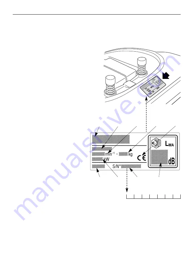
The plate located near the battery hou-
sing has the essential data of each
machine.

The serial number (7) must be quoted
when you require technical assistance or
spare parts.

1.

Acoustic power level accor-

ding to directive 2000/14/CE

2.

Conformity mark according to
directive 98/37/EEC

3.

Year of manufacture

4.

Nominal power (if indicated)

5.

Operating engine speed

in r.p.m

6.

Type of machine

7.

Serial number

8.

Weight in kg

9.

Name and address of 
Manufacturer

2.2 IDENTIFICATION OF MAIN COMPONENTS

Various main components can be seen on the machine, and these have the fol-
lowing functions:

11. Cutting deck: 

this is the guard enclosing the rotating blades. There can be

EN 7

IDENTIFICATION OF THE MACHINE AND COMPONENTS

Note your machine serial number here

3

4

7

1

6

9

5

8

2

Summary of Contents for EF102C/15,5H

Page 1: ...group 42011 BAGNOLO IN PIANO REGGIO EMILIA ITALY TEL 0522 956611 TELEFAX 0522 951555 EMAIL service emak it INTERNET http www emak it 71505056 0 IT DE GEBRUIKERSHANDLEIDING NL MANUEL D UTILISATION FR O...

Page 2: ...a garanzia e il declino di ogni responsabilit del Costruttore riversando sull utilizzatore gli oneri derivanti da danni o lesioni proprie o a terzi Nel caso dovesse riscontrare qualche leggera differe...

Page 3: ...ioni preliminari prima di iniziare il lavoro 22 5 4 Uso della macchina 25 5 5 Uso sui terreni in pendenza 34 5 6 Trasporto 34 5 7 Alcuni consigli per eseguire un buon taglio 35 6 MANUTENZIONE 36 Conti...

Page 4: ...ne continua idro statica della velocit I modelli a trasmissione idrostatica sono riconoscibili dalla scritta HYDRO apposta sull etichetta di identificazione 2 1 presenza di componenti o accessori non...

Page 5: ...ndossare sempre calzature solide e pantaloni lunghi Non aziona re la macchina a piedi scalzi o con sandali aperti 2 Ispezionare a fondo tutta l area di lavoro e togliere tutto ci che potrebbe venire e...

Page 6: ...ogliatore di scarico prima di controllare pulire o lavorare sulla macchina dopo aver colpito un corpo estraneo Verificare eventuali danni sulla macchina ed effettuare le necessarie riparazioni prima d...

Page 7: ...ondo le istruzioni fornite Nell uso non superare i limiti di carico riportati sull etichet ta e rispettare le norme di sicurezza 1 2 C 6 IT 6 NORME DI SICUREZZA Attenzione Leggere le istru zioni prima...

Page 8: ...formit secondo la direttiva 98 37 CEE 3 Anno di fabbricazione 4 Potenza nominale se indicata 5 Velocit di esercizio del motore in giri min 6 Tipo di macchina 7 Numero di matricola 8 Peso in kg 9 Nome...

Page 9: ...i oggetti raccolti dalle lame di essere scagliati lontano dalla macchina 16 Motore fornisce il movimento sia delle lame che della trazione alle ruote le sue caratteristiche e norme d uso sono descritt...

Page 10: ...a macchina vera e propria il volante il sedile i supporti del sacco i componenti del sacco una busta con i manuali d istruzioni e i documenti la dotazione viteria comprendente anche la spina di blocca...

Page 11: ...dal lato del volante fino ad agganciarlo in una delle sei posizioni A questo punto il sedile risulta montato stabilmente e non pu pi essere sfilato se non premendo la leva 4 che lo libera dall arresto...

Page 12: ...per ciascun supporto tre viti 3 in dotazione come indicato senza bloccare i relativi dadi 4 Agganciare ai supporti la parte superiore 5 del telaio del sacco e centrarla rispetto alla piastra posterio...

Page 13: ...montaggio dei supporti del sacco e non deve pi essere utilizzato 3 7 MONTAGGIO DEL SACCO Il montaggio del sacco deve essere eseguito in quattro fasi A Montare per prima cosa il telaio unendo la parte...

Page 14: ...elaio aiu tandosi con un cacciavite 8 C Introdurre la maniglia 9 nei fori della copertura 10 fissare il tutto al telaio mediante le viti 11 come indicato e le viti autofilettanti posteriori 12 D Appli...

Page 15: ...cchimento della miscela e deve essere utilizzato solo per il tempo strettamente necessario in caso di avviamento a freddo 4 3 LEVA ACCELERATORE Regola il numero dei giri del motore Le posizioni indica...

Page 16: ...tutto spento MARCIA tutti i servizi attivati AVVIAMENTO inserisce il motorino di avviamento Rilasciando la chiave dalla posizione AVVIAMENTO questa torna automatica mente in posizione MARCIA 4 5 LEVA...

Page 17: ...rificazione del motore f mancanza del sacco o del parasassi g insufficiente ricarica della batteria h trasmissione in folle Il segnale acustico pu essere di due tipi a continuo segnala l intervento de...

Page 18: ...e lame vengono innestate senza rispettare le condizioni di sicurezza previste il motore si spegne o non pu essere avviato 5 2 La condizione di Lame innestate segnalata dall accensione della spia 4 7 a...

Page 19: ...smissione del moto Durante la marcia bene non tenere il pie de appoggiato sul pedale 4 22 LEVA COMANDO CAMBIO DI VELOCIT Questa leva ha sette posizioni corrispondenti alle cinque marce in avanti alla...

Page 20: ...all accensione della spia 4 7 h L inserimento della retromarcia deve avveni re da fermo Se il pedale della trazione viene azionato sia in avanti che in retromarcia con il freno di stazionamento 4 5 in...

Page 21: ...ilit dell utilizzatore la valutazione dei rischi potenziali del terreno su cui si deve lavorare nonch prendere tutte le precauzioni necessarie per garantire la sua e altrui sicurezza in particola re s...

Page 22: ...N Inserito Fermo Seduto NO Disinnestate N Disinserito Fermo B AVVIAMENTO Chiave in posizione AVVIAMENTO Seduto Disinnestate 1 5 F R Inserito NON si avvia Seduto Innestate N Inserito NON si avvia Asse...

Page 23: ...2 PRESSIONE DEI PNEUMATICI La corretta pressione dei pneumatici condizione essenziale per ottenere un perfetto allineamento del piatto di taglio e quindi una rasatura uniforme del prato Togliere i cop...

Page 24: ...ON AVVICINARE FIAMME ALLA BOCCA DEL SERBATOIO PER VERIFICARE IL CONTENUTO E NON FUMARE DURANTE IL RIFORNI MENTO 5 3 4 MONTAGGIO DELLE PROTEZIONI ALL USCITA SACCO O PARASASSI Non utilizzare mai la macc...

Page 25: ...ENANTE Assicurarsi che la capacit di frenata della macchina sia adeguata alle condizioni di impiego evitando di iniziare il lavoro se si nutrono dubbi sulla efficienza del freno Nel caso di necessit r...

Page 26: ...ndi portarla in posizione AVVIAMENTO per avviare il motore rilasciare la chiave ad avviamento avvenuto A motore avviato portare l acceleratore in posizione di LENTO e disinserire lo starter se previst...

Page 27: ...premuto il pedale disinserire il freno di stazionamento rilasciare gra dualmente il pedale che passa cos dalla funzione freno a quella di frizio ne azionando le ruote posteriori 4 21 Il rilascio deve...

Page 28: ...mo Nei modelli a trasmissione meccanica Azionare il pedale fino ad arrestare la macchina inserire la retromarcia spo stando lateralmente la leva e portandola in posizione R 4 22 Rilasciare gradualment...

Page 29: ...CE portare il piatto di taglio in posizione di massima altezza innestare le lame 4 9 iniziare l avanzamento nella zona erbosa in modo molto graduale e con parti colare cautela come gi descritto preced...

Page 30: ...le acustico intermittente segnala il riem pimento del sacco a questo punto ridurre il regime del motore mettere in folle N 4 22 oppure 4 32 ed arrestare l avanzamento inserire il freno di stazionament...

Page 31: ...l motore portan do la chiave in posizione ARRESTO A motore spento chiudere il rubinetto 1 della benzi na se previsto Nel caso di motore 12 12 5 13 5 HP B S per evitare possibili ritorni di fiamma port...

Page 32: ...he il piatto di taglio si trovi completamente abbassato Togliere poi il sacco svuotarlo risciacquarlo e riporlo in modo da favorire una rapida asciugatura Nei modelli con innesto elettromagnetico Per...

Page 33: ...ratore 5 4 12 ALCUNE INFORMAZIONI UTILI A Dispositivo di protezione della scheda La scheda elettronica munita di una protezione autoripristinante che interrompe il circuito in caso di anomalie nell im...

Page 34: ...mere in avanti il pedale della trazione 4 32 Ridurre i giri del motore e premere il pedale del freno Arrestare la macchina nei modelli a trasmissione meccanica mettere in folle N premere a fondo il pe...

Page 35: ...ella macchina Ridurre la velocit d avanzamento prima di affrontare un pendio special mente in discesa Non inserire mai la retromarcia per ridurre la velocit in discesa questo potrebbe causare la perdi...

Page 36: ...spinta dell erba tagliata attraver so il canale d espulsione 5 La frequenza delle rasature deve essere rapportata alla crescita dell erba evi tando che tra un taglio e l altro l erba cresca troppo 6...

Page 37: ...inante 6 1 1 POSIZIONAMENTO IN VERTICALE Qualora fosse necessario accedere comodamente alla parte inferiore possibile posizionare la macchina in verticale Disporre la macchi na su un terreno solido e...

Page 38: ...i schemi che riportano i punti soggetti a verifiche lubrificazione e manutenzione periodiche con l indicazione del tipo di lubrificante da impiegare e della periodicit da osservare negli interventi a...

Page 39: ...IT 38 MANUTENZIONE b Lubrificazione Nei modelli a trasmissione meccanica GRASSO OLIO SAE 30 Nei modelli a trasmissione idrostatica...

Page 40: ...llo cinghia comando lame 25 1 6 Sostituzione cinghia comando lame 2 1 7 Controllo cinghia collegamento lame 25 1 8 Sostituzione cinghia collegamento lame 2 1 9 Controllo e registrazione freno 10 1 10...

Page 41: ...della vostra macchina deve essere tassativamente caricata prima del primo utilizzo e successivamente in caso di inattivit della macchina e alla suc cessiva messa in servizio Leggere e rispettare atte...

Page 42: ...il prato Indossare guanti robusti per maneggiare le lame Per smontare una lama afferrarla salda mente e svitare la vite centrale 1 nel senso indicato dalla freccia per ciascu na lama in quanto le vit...

Page 43: ...l coltello serra re bene a fondo le viti di fissaggio 2 meglio se impiegando una chiave dinamometrica tarata a 45 50 Nm Qualora nello smontaggio della lama si fosse sfilato il mozzo 3 dall albero acce...

Page 44: ...estra che a sinistra quindi bloccare i relativi controdadi 6 Nel caso non si riuscisse ad ottenere una buona regolazione consultare un Centro di Assistenza Autorizzato 6 3 3 REGOLAZIONE DELL INNESTO E...

Page 45: ...del freno La registrazione deve avvenire con il freno di stazionamento inserito L accesso alla regola zione possibile togliendo lo sportello posto sul tunnel alla base del sedile Allentare il dado 1...

Page 46: ...e una lunghezza A della molla 3 di A 114 116 mm Nei modelli a trasmissione meccanica A 109 111 mm Nei modelli a trasmissione idrostatica misurata all esterno delle spire Bloccare i dadi 2 a regolazion...

Page 47: ...sso diametro e verificare la regolazione del parallelismo del piatto di taglio per evitare tagli irregolari Prima di rimontare una ruota spalmare l asse con del grasso e riposizionare accuratamente l...

Page 48: ...uno di uguale tipo e portata e mai con uno di portata diversa Nel caso non si riesca ad eliminare le cause di intervento consultare un Centro di Assistenza Autorizzato 6 4 5 SOSTITUZIONE DELLE CINGHI...

Page 49: ...afflusso di benzina difetto di accensione problemi di carburazione velocit di avanzamento elevata in rap porto all altezza di taglio 5 4 5 Mettere la chiave in pos ARRESTO e cercare le cause del guas...

Page 50: ...mancanza di massa sul motore problemi al motore la leva non ritorna in posizione di disin nesto a causa di accumuli d erba nel punto di fine corsa cavo allungato o cinghia allentata sedersi correttam...

Page 51: ...ntoo del piatto rispetto al terreno 6 3 2 controllare il corretto montaggio delle lame 6 3 1 affilare o sostituire le lame 6 3 1 controllare la tensione della cinghia e il filo di comando della leva d...

Page 52: ...un rimorchietto 4 TELO DI COPERTURA Protegge la macchina dalla polvere quando non viene utilizzata 5 CARICA BATTERIE DI MANTENIMENTO CB01 Permette di mantenere la batteria in buona efficien za durant...

Page 53: ...Marcia avanti da 0 a 8 8 km h in Retromarcia da 0 a 4 5 km h Impianto elettrico 12 V Batteria 18 Ah Pneumatici anteriori 13 x 5 00 6 oppure 15 x 5 00 6 Pneumatici posteriori 18 x 8 50 8 Pressione gon...

Page 54: ...5 6 Trazione alle ruote Regolazione della cinghia 6 3 5 Volante Funzione 4 1 Montaggio sulla macchina 3 2 Acceleratore Funzione e uso 4 3 Avviamento Procedura per l avviamento 5 4 1 Batteria Descrizio...

Page 55: ...invalidate the guarantee and the manufacturer will decline all responsibility placing the blame with the user for damage or injury to himself or others in such cases Since the product is continually...

Page 56: ...evices cut in 20 5 3 Preliminary operations before starting work 22 5 4 Using the machine 25 5 5 Using on slopes 34 5 6 Transporting 34 5 7 Advice on how to obtain a good cut 35 6 MAINTENANCE 36 All t...

Page 57: ...s with hydrostatic transmission can be recognised by the word HYDRO on the identification label 2 1 the inclusion of components or accessories which may not be available in some areas special equipmen...

Page 58: ...B PREPARATION 1 While mowing always wear substantial footwear and long trousers Do not operate the equipment when barefoot or wearing open sandals 2 Thoroughly inspect the area where the equipment is...

Page 59: ...brake stop the engine and remove the key 11 Disengage drive to attachments stop the engine and remove the ignition key before clearing blockages or unclogging chutes before cleaning checking or workin...

Page 60: ...the recommended draw bar loads stated on the decal and follow the safety instruc tions 1 2 C 6 EN 6 SAFETY Warning Read the Operator s Manual before operating this machine Warning Disconnect the igni...

Page 61: ...ty mark according to directive 98 37 EEC 3 Year of manufacture 4 Nominal power if indicated 5 Operating engine speed in r p m 6 Type of machine 7 Serial number 8 Weight in kg 9 Name and address of Man...

Page 62: ...jects drawn up by the blades from being thrown outside of the machine 16 Engine this moves the blades and drives the wheels Its specifications and regulations for use are described in a specific manua...

Page 63: ...g contents the machine the steering wheel the seat the grass catcher brackets the grass catcher components an envelope containing the operator s manuals and documents the nuts and bolts including a pi...

Page 64: ...wheel s side till the seat engages in one of the 6 positions At this point the seat is engaged and can not be completely removed unless the lever 4 is pressed freeing it from its retainer Connect the...

Page 65: ...for each bracket three screws 3 which are supplied as shown without fully tightening the nuts 4 Hook the upper part of the grass catcher frame 5 onto the brackets and centre it up with the rear plate...

Page 66: ...g the grass catcher brackets and is not to be subsequently used 3 7 GRASS CATCHER ASSEMBLY The grass catcher is assembled in four stages A First of all assemble the frame joining the upper part 1 to t...

Page 67: ...d of a screw driver 8 C Insert the handle 9 into the holes of the canvas cover 10 Attach this to the frame using the screws 11 following the indicated sequence and then the self threading screws 12 at...

Page 68: ...nriches the mixture so must only be used for the time necessary when star ting from cold 4 3 ACCELERATOR LEVER Regulates the engine s r p m The positions are indicated on a plate showing the EN 14 CON...

Page 69: ...s three positions OFF everything is switched off ON activates all parts START engages the starter motor On being released at the START position the key will automatically return to ON 4 5 PARKING BRAK...

Page 70: ...ss catcher or stone guard g insufficient battery recharge h transmission in neutral position There are two types of audible warning a continuous the electronic card s protection device has cut in b in...

Page 71: ...If the blades are engaged when safety conditions have not been complied with the engine shuts down and cannot be restarted 5 2 The Blades engaged condition is indicated by a pilot lamp 4 7 a On disen...

Page 72: ...mission belt When the machine is in movement keep your foot off the pedal 4 22 SPEED CHANGE LEVER This lever has seven positions for the 5 forward speeds the neutral position N and reverse R To go fro...

Page 73: ...ighting of a pilot lamp 4 7 h Reverse must only be engaged when the machine is stopped If the drive pedal is used whether forwards or for reverse when the parking brake 4 5 is engaged the engine stops...

Page 74: ...ons and your ability to concentrate It is the user s responsibility to assess the potential risk of the area where work is to be carried out as well as to take all the necessary steps to ensure his ow...

Page 75: ...PILOT LAMPS A PILOT LAMPS ON Key in ON position Sitting YES Disengaged N Engaged Stopped Sitting NO Disengaged N Disengaged Stopped B WHEN STARTING Key in START position Sitting Disengaged 1 5 F R En...

Page 76: ...at along to the notch of the position wanted 5 3 2 TYRE PRESSURE Having the correct tyre pressure is the main condition for ensuring that the cut ting deck is horizontal and thus mows evenly Take off...

Page 77: ...AME TO THE TANK S OPENING IN ORDER TO SEE THE TANK S CONTENTS AND DO NOT SMOKE WHEN REFUELLING 5 3 4 FITTING THE PROTECTION AT THE EXIT GRASS CATCHER OR STONE GUARD Never use the machine without havin...

Page 78: ...n 5 3 6 CHECKING THE BRAKING SYSTEM Make sure that the machine s braking capacity is adequate for the conditions of usage Avoid starting the machine if you have doubts on the brake efficiency If neces...

Page 79: ...t the engine release the key once the engine has started When the engine has started put the accelerator in the SLOW position and close the choke if fitted The choke must be closed as soon as the engi...

Page 80: ...4 22 Keep the pedal pressed down and disengage the parking brake Slowly relea se the pedal which will turn from brake to clutch thus operating the rear wheels 4 21 The pedal has to be released gradual...

Page 81: ...mechanical drive models Push down the pedal until the machine stops and then insert reverse by moving the lever sideways and putting it into position R 4 22 Gradually release the pedal to engage the c...

Page 82: ...put the accelerator into the FAST position bring the cutting deck to the highest position engage the blades 4 9 start moving forwards onto the grass area very gradually and with particular caution as...

Page 83: ...When the grass catcher is full there is an intermit tent audible warning At this point lower the engine speed go into neutral N 4 22 or 4 32 and stop forward movement engage the parking brake on slop...

Page 84: ...rator lever in the SLOW position and turn off the engine by putting the key into the OFF position When the engine is stopped close the fuel stopcock 1 if fitted With 12 12 5 13 5 HP B S engines to avo...

Page 85: ...k should be in the fully lowered position Take off the grass catcher empty and rinse it and then put it in a position where it can dry quickly For models with electromagnetic clutch To avoid umpairing...

Page 86: ...ATION A Card protection device The electronic card has a self resetting protector which breaks the circuit if there is a fault in the electrical system It results in the stopping of the engine and an...

Page 87: ...dels press the drive pedal forward 4 32 Reduce the engine speed and press the brake pedal Stop the machine for mechanical drive models put into neutral push the pedal right down engage reverse 4 22 an...

Page 88: ...on sloping ground to prevent the risk of tipping up Reduce the forward speed befo re going on a slope particularly downhill Never use reverse to reduce speed going downhill Con trol of the machine may...

Page 89: ...The frequency of mowing should be in relation to the rate of growth of the grass which should not be left to grow too much between one cut and the next 6 During hot and dry periods the grass should be...

Page 90: ...n unauthori sed places 6 1 1 LIFTING THE MACHINE VERTICALLY If you need to have easy access to the lower part of the machine it is possible to lift it vertically Place the machine on firm and flat gro...

Page 91: ...ATION Follow the diagrams which show the points requiring checks lubricating and rou tine maintenance together with the type of lubricant to be used and the frequency required a Periodic maintenance 6...

Page 92: ...EN 38 MAINTENANCE b Lubrification For mechanical drive models GREASE OIL SAE 30 For hydrostatic drive models...

Page 93: ...ive belt 25 1 6 Blade drive belt replacement 2 1 7 Check the belt connecting blades 25 1 8 Replacement of belt connecting blades 2 1 9 Check and adjustment of brake 10 1 10 Check and adjustment of dri...

Page 94: ...chine must be charged before using for the first time and subsequently if the machine is stored before the next time of starting up To ensure long life to the battery it is essential to keep it carefu...

Page 95: ...move a blade hold it firmly and undo the central bolt 1 in the direction indi cated by the arrow for each blade noting that one of the fixing bolts has a right hand thread and the other one has a left...

Page 96: ...facing towards the interior of the cutting deck and that the cupped side of the cup washer 1 is pres sing against the blade Fully tigh ten the fixing screws 2 prefera bly using a torque wrench set at...

Page 97: ...If you are unable to get the cutting deck adju sted properly consult a Licensed Service Cen tre 6 3 3 ADJUSTMENT TO THE ENGAGEMENT AND BRAKE OF THE BLADES For models with lever operated engagement Wh...

Page 98: ...will need to be adjusted The adjustment will need to be made while the parking brake is engaged Access for making this adjustment is by taking off the inspection hatch beneath the seat Loosen the nut...

Page 99: ...f A 114 116 mm For mechanical drive models A 109 111 mm For hydrostatic drive models measured to the outside of the end of the spring When the adjustment has been made tighten the nuts 2 When replacin...

Page 100: ...s ensure that they are of the same diameter and check that cutting deck is horizontal to pre vent an uneven cut Before re fitting a wheel smear some waterproof grease on the axle and carefully re fit...

Page 101: ...ame type and ampere rating and never with one of another rating If you cannot find out why the fuse has blown consult a Licensed Service Centre 6 4 5 REPLACING BELTS Replacing belts is quite a complic...

Page 102: ...charged battery faulty fuel supply faulty ignition fault in carburation forward speed too high in relation to cutting height 5 4 5 Put the key in the OFF position and look for the cause of the proble...

Page 103: ...or contact engine badly earthed battery disconnected no earth contact on engine problems in the engine the lever does not return to the disen gaged position due to accumulated grass cuttings at the en...

Page 104: ...check that the blades are fitted pro perly 6 3 1 sharpen or fit new blades 6 3 1 check the tension of the belt and con trol cable of the blade engagement lever models with lever engage ment 6 3 3 red...

Page 105: ...ed 3 TOWING HITCH For towing a small trailer 4 CLOTH COVER Protects the machine from dust when not in use 5 CB01 MAINTENANCE BATTERY CHARGER This makes it possible to keep the battery in good working...

Page 106: ...8 km h in Reverse from 0 to 4 5 km h Electrical system 12 V Battery 18 Ah Front tyres 13 x 5 00 6 or 15 x 5 00 6 Rear tyres 18 x 8 50 8 Front tyre pressure tyres 13 x 5 00 6 1 5 bar tyres 15 x 5 00 6...

Page 107: ...Tyres Pressures 5 3 2 Repair and replacement 6 4 2 Wheels Replacement 6 4 1 Accelerator Function and use 4 3 Audible warning Function 4 7 When it signals 5 4 6 5 4 12 Battery Description 2 2 17 Conne...

Page 108: ...abricante siendo el usuario responsable por da os o lesiones propias o a terceros En caso de que encontrara alguna leve diferencia entre lo descrito en este manual y la m quina en su poder tenga prese...

Page 109: ...d 20 5 3 Operaciones preliminares antes de comenzar el trabajo 22 5 4 Uso de la m quina 25 5 5 Uso de la m quina en pendientes 34 5 6 Transporte 34 5 7 Consejos para efectuar un buen corte del c sped...

Page 110: ...regulaci n hidrost tica continua de la velocidad Los modelos con transmisi n hidrost tica se identifican con la inscrip ci n HYDRO presente en la etiqueta de identificaci n 2 1 la presencia de compon...

Page 111: ...NARES 1 Durante el corte utilizar siempre calzado robusto y pantalones largos No utilizar la m quina con los pies descalzos o con sandalias abiertas 2 Inspeccionar a fondo toda el rea de trabajo y qui...

Page 112: ...ve 11 Desacoplar las cuchillas apagar el motor y quitar la llave antes de limpiar desatascar el transportador de salida antes de controlar limpiar o trabajar con la m quina despu s de golpear un cuerp...

Page 113: ...radas Cuando se utiliza el remolque no superar los limites de carga indicados en la etiqueta y respetar las normas de seguridad 1 2 C 6 ES 6 NORMAS DE SEGURIDAD Atenci n Leer las instruccio nes antes...

Page 114: ...arca de conformidad seg n la directiva 98 37 CEE 3 A o de fabricaci n 4 Potencia nominal si indicada 5 R gimen de trabajo del motor en r p m 6 Tipo de m quina 7 N mero de matr cula 8 Peso en kg 9 Nomb...

Page 115: ...e eventuales objetos recogidos por las cuchillas puedan ser lanzados lejos de la m quina 16 Motor suministra el movimiento ya sea a las cuchillas como a la tracci n a las ruedas Sus caracter sticas se...

Page 116: ...quina propiamente dicha el volante el asiento los soportes de la bolsa de recolecci n los componentes de la bolsa un sobre con manual de instrucciones y documentaci n la dotaci n de tornillos que con...

Page 117: ...asta que se enganche en una de las seis posiciones En este momento el asiento est montado de manera estable y no se puede extraer completamente si no se aprieta la corre spondiente palanca 4 que lo de...

Page 118: ...soporte los tres tornillos 3 suministrados en dota ci n como se indica sin fijar las relativas tuercas 4 Enganchar en los soportes la parte superior 5 del bastidor de la bolsa y centrarlo respecto a...

Page 119: ...ontaje de los soportes de la bolsa y no se deber utilizar m s 3 7 MONTAJE DE LA BOLSA DE RECOLECCION El montaje de la bolsa de recolecci n se debe ejecutar en cuatro fases A En primer lugar montar el...

Page 120: ...estornillador 8 C Introducir el asa 9 en los orificios de la cubierta 10 fijar el conjunto al bastidor mediante los tornillos 11 en la secuencia indicada y completar el montaje con los tornillos autor...

Page 121: ...quecimiento de la mezcla y se debe utilizar s lo por el tiempo estric tamente necesario para el arranque en fr o del motor 4 3 PALANCA DEL ACELERADOR Regula el n mero de revoluciones del motor Las pos...

Page 122: ...es PARADA corresponde a todo apagado MARCHA activa todos los servicios ARRANQUE acciona el motor de arranque Soltando la llave de la posici n ARRANQUE la misma regresa autom ticamente a la posici n MA...

Page 123: ...ausencia de la bolsa de recolecci n o de la pantalla protecci n g carga de la bater a insuficiente h avance en punto muerto La se al ac stica puede ser de dos tipos a continua indica intervenci n del...

Page 124: ...Si las cuchillas son acopladas sin respetar las condiciones de seguridad previs tas el motor se apaga o no se puede arrancar 5 2 El encendido del indicador 4 7 a se ala la condici n de Cuchillas acopl...

Page 125: ...marcha es aconsejable no tener el pie apoyado sobre el pedal 4 22 PALANCA DE MANDO DEL CAMBIO DE VELOCIDAD Esta palanca tiene siete posiciones correspondientes a las cinco marchas hacia adelante a la...

Page 126: ...ci n de Punto muerto N La marcha atr s se debe engranar con la m quina parada Si el pedal de la tracci n es accionado en marcha adelante y en marcha atr s con el freno de estacionamiento engranado 4 5...

Page 127: ...es responsable de la evaluaci n de los riesgos poten ciales del terreno sobre el cual se debe trabajar as como de tomar todas las precauciones necesarias para garantizar su seguridad y la de terceros...

Page 128: ...RENO MOTOR INDICADORES A CUADRO CONECTADO Llave en la posici n MARCHA Sentado SI Desacopladas N Engranado Parado Sentado NO Desacopladas N Desengranado Parado B ARRANQUE Llave en la posici n ARRANQUE...

Page 129: ...OS La correcta presi n de los neum ticos es una condici n esencial para una perfecta alineaci n del plato de corte y por lo tanto para obtener un c sped cortado uniforme mente Quitar las tazas si prev...

Page 130: ...R LLAMAS A LA BOCA DEL DEPOSITO PARA VERIFICAR EL CONTENIDO Y NO FUMAR DURANTE EL LLENADO 5 3 4 MONTAJE DE LAS PROTECCIONES A LA SALIDA BOLSA DE RECOLECCION O PANTALLA DE PROTECCION No utilizar jam s...

Page 131: ...NOS Comprobar que la capacidad de frenado de la m quina sea adecuada a las condicio nes de funcionamiento evitando comenzar el trabajo en caso de dudas sobre la efi ciencia del sistema de frenos Si es...

Page 132: ...a posici n ARRANQUE para arrancar el motor soltar la llave despu s de la puesta en marcha Despu s de la puesta en marcha del motor llevar el acelerador a la posici n LENTO y desconectar el cebador si...

Page 133: ...4 22 Manteniendo apretado el pedal quitar el freno de estacionamiento soltar gra dualmente el pedal que de ese modo pasa de la funci n freno a la de embrague accionando las ruedas posteriores 4 21 Sol...

Page 134: ...arada En los modelos de transmisi n mec nica La marcha atr s se debe engranar con la m quina parada Accionar el pedal hasta detener la m quina aplicar la marcha atr s moviendo lateralmente la palanca...

Page 135: ...menzar el corte poner el acelerador en la posici n RAPIDO llevar el plato de corte a la posici n de altura m xima acoplar las cuchillas 4 9 iniciar el avance en el c sped en modo muy gradual y con par...

Page 136: ...stica intermitente indica que se ha lle nado la bolsa A este punto ejecutar lo siguiente reducir el r gimen del motor poner la transmisi n en punto muerto N 4 22 o 4 32 parar el avance engranar el fr...

Page 137: ...do la llave a la posici n PARADA Con el motor apagado cerrar el grifo 1 de la gasolina si previsto En caso de motor 12 12 5 13 5 HP B S para prevenir eventuales llamas de retroceso llevar el acelerado...

Page 138: ...Durante el lavado es oportuno que el plato de corte se encuentre completamente bajado Sacar luego el plato vaciarlo enjuagarlo y colocarlo de manera que se seque r pidamente En los modelos con acoplam...

Page 139: ...a est provista de una protecci n de reposici n autom tica que interrumpe el circuito en caso de anomal as en la instalaci n el ctrica La interven ci n produce la parada del motor indicada por una se a...

Page 140: ...l r gimen del motor y apretar el pedal del freno Parar la m quina en los modelos de transmisi n mec nica Poner la m quina en punto muerto apretar a fondo el pedal engra nar la marcha atr s 4 22 y solt...

Page 141: ...se pueda empinar Disminuir la velocidad de avance antes de comenzar una pendiente especial mente en bajada No engranar nunca la marcha atr s para reducir la veloci dad en las pendientes porque podr a...

Page 142: ...l si n 5 La frecuencia del corte debe ser adecuada al crecimiento del c sped evitando que entre un corte y el otro el c sped crezca demasiado 6 En los periodos m s calurosos y secos es aconsejable man...

Page 143: ...ina o cualquier otro producto contaminante 6 1 1 COLOCACION VERTICAL Si es necesario acceder c modamente a la parte inferior es posible colocar la m qui na en vertical Colocar la m quina en un terreno...

Page 144: ...indican los puntos en los que hay que efectuar com probaciones lubricaciones y operaciones de mantenimiento peri dico con la indica ci n del tipo de lubricante a utilizar y de la frecuencia de dichas...

Page 145: ...ES 38 MANTENIMIENTO b Lubricaci n En los modelos de transmisi n mec nica GRASA ACEITE SAE 30 En los modelos de transmisi n hidrost tica...

Page 146: ...25 1 6 Sustituci n correa mando cuchillas 2 1 7 Control correa conexi n cuchillas 25 1 8 Sustituci n correa conexi n cuchillas 2 1 9 Control y regulaci n del freno 10 1 10 Control y regulaci n de la...

Page 147: ...uraci n de la misma La bater a de su m quina debe ser absolutamente cargada antes del primer uso y en lo sucesivo regularmente en caso de inactividad de la m quina y la sucesiva pue sta en servicio Le...

Page 148: ...para manipular las cuchillas Para desmontar una cuchilla cogerla firme mente y desenroscar el tornillo central 1 en el sentido indicado por las flechas para cada cuchilla ya que los tornillos de fijac...

Page 149: ...que la parte c ncava del disco el stico 1 apriete contra el cuchillo Ajustar bien a fondo los tornillos de fijaci n 2 utilizando preferentemente una llave dina mom trica calibrada a 45 50 Nm Si durant...

Page 150: ...ier da Luego fijar las relativas contratuercas 6 Si no se logra obtener una buena regulaci n consultar un Centro de Asistencia Autorizado 6 3 3 REGULACION DEL ACOPLAMIENTO Y FRENO DE LAS CUCHILLAS En...

Page 151: ...el resorte del freno La regulaci n se debe efectuar con el freno de estacionamiento engranado Es posible acceder a la regulaci n sacando la portezuela colocada en el t nel a la base del asiento Afloja...

Page 152: ...3 A 114 116 mm en los modelos con transmisi n mec nica A 109 111 mm en los modelos con transmisi n hidrost tica medida dentro de las espiras Despu s de haber efectuado la regulaci n fijar las tuercas...

Page 153: ...ue sean del mismo di metro y comprobar la regulaci n del paraleli smo del plato de corte para prevenir cortes irregulares Antes de montar una rueda untar el eje con grasa y volver a colocar cuidadosam...

Page 154: ...carga y jam s con uno de carga diferente Si no se logra eliminar las causas de la intervenci n consultar un Centro de Asisten cia Autorizado 6 4 5 SUSTITUCION DE LAS CORREAS Para la sustituci n de la...

Page 155: ...ente cargada falta flujo de gasolina defecto del encendido anomal as en el carburador velocidad de avance elevada en rela ci n a la altura del corte 5 4 5 Poner la llave en la pos PARADA y buscar las...

Page 156: ...a bater a desconectada falta masa en el motor anomal as en el motor la palanca no regresa a la posici n de desacoplamiento a causa de la hierba acumulada en el punto en correspon dencia del fin de car...

Page 157: ...orte respecto al terreno 6 3 2 controlar el correcto montaje de las cuchillas 6 3 1 afilar o sustituir las cuchillas 6 3 1 controlar la tensi n de la correa y el hilo de comando de la palanca de aco p...

Page 158: ...T REMOLQUE Para remolcar un remolque 4 LONA DE CUBIERTA Para proteger la m quina contra el polvo cuando no es utilizada 5 CARGADOR DE BATERIA DE MANTENIMIENTO CB01 Permite mantener en perfecta eficaci...

Page 159: ...h en marcha atr s 0 4 5 km h Instalaci n el ctrica 12 V Bater a 18 Ah Neum ticos anteriores 13 x 5 00 6 15 x 5 00 6 Neum ticos posteriores 18 x 8 50 8 Presi n neum tico anterior neum tico 13 x 5 00 6...

Page 160: ...e Modo de ejecuci n 5 6 Volante Funci n 4 1 Montaje en la m quina 3 2 Abastecimientos Modo de abastecimiento 5 3 3 Acelerador Funci n y uso 4 3 Arranque Procedimiento para el arranque 5 4 1 Asiento De...

Reviews: