94
Chapter 3
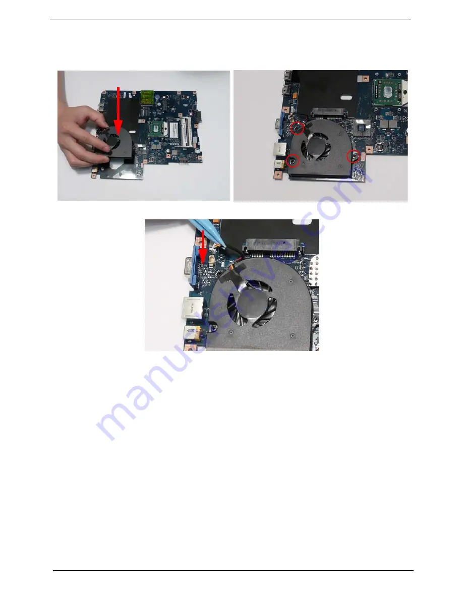
Replacing the CPU Fan
Replacing the Thermal Module
IMPORTANT:
Apply a suitable thermal grease and ensure all heat pads are in place before replacing the Thermal
Module.
The following thermal grease types are approved for use:
•
Silmore GP50
•
Honeywell
•
Jet Motor 7762
The following thermal pads are approved for use:
•
Eapus XR-PE
1.
Align the screw holes on the CPU Fan and
Mainboard and replace the Fan.
2.
Replace the three (3) screws to secure the Fan to
the Mainboard.
3.
Connect the Fan power cable to the Mainboard connector.
1.
Remove all traces of thermal grease from the CPU using a lint-free cloth or cotton swab and Isopropyl
Alcohol, Acetone, or other approved cleaning agent.
2.
Apply a small amount of thermal grease to the centre of the CPU—there is no need to spread the grease
manually, the force used during the installation of the Thermal Module is sufficient.
Summary of Contents for G430 Series
Page 6: ...VI ...
Page 10: ...X Table of Contents ...
Page 13: ...Chapter 1 3 System Block Diagram ...
Page 68: ...58 Chapter 3 4 Disconnect the following four 4 cables from the Mainboard A B C D ...
Page 81: ...Chapter 3 71 4 Using both hands lift the Thermal Module clear of the Mainboard ...
Page 83: ...Chapter 3 73 4 Lift the CPU Fan clear of the Mainboard as shown ...
Page 89: ...Chapter 3 79 5 Lift the LCD Panel clear of the module ...
Page 97: ...Chapter 3 87 9 The Antennas and cables appear as shown when correctly installed ...
Page 102: ...92 Chapter 3 2 Replace the four 4 screws and screw caps provided ...
Page 107: ...Chapter 3 97 5 Replace the FFC and press down as indicated to secure it to the Upper Cover ...
Page 118: ...108 Chapter 3 17 Replace the two 2 screws securing the LCD Module to the Lower Cover ...
Page 126: ...116 Chapter 3 ...
Page 154: ...144 Chapter 6 eMachines G630 G430 Exploded Diagrams Main Assembly 1 2 3 4 5 ...
Page 165: ...Chapter 6 155 ...
Page 186: ...Appendix A 176 ...
Page 192: ...182 Appendix B ...
Page 194: ...184 Appendix C ...
Page 198: ...188 ...


