\\Elmacron-server\Gemensam\Instruktioner\Instruktioner i W ord\1005RE\Engelska\1005RE-ORP%E.doc
- 4 -
-
Senast utskrivet 2007-10-11
11:16
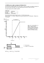
2.3.2 Connection of the power supply
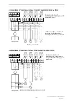
Connect the power supply to terminal 1 (earth), terminal 2 (zero) and terminal 3 (live).
2.3.3 Connection of dosing pumps and valves ( control outputs )
Connection to relay output 1 (X1) is made through terminal 4 and terminal 6, connection to relay
output 2 (X2) is made through terminal 7 and terminal 9, connection to relay output 3 (L1) is made
through terminal 10 and terminal 12 and connection to relay output 4 (L2) is made through terminal 13
and terminal 15.
2.3.4 Connection to an external alarm
Connect alarm to terminal 16 and terminal 18.
2.3.5 Connection of the electrode
Electrode cabling is a very critical part for the safety and accuracy in measuring.
•
Use a low noise coax cable between the electrode and the input terminal on the controller.
•
Low noise cables has, in general, a black semi-conductive sheath between the centrewire
insulation and the shield. Remove this sheath.
•
Keep the cable away from power wires.
•
Max recommended length of cable is 10 meters.
•
Connect the centre ( metal pin ) of the coax cable to terminal 19 ( ELCT + ).
•
Connect the shield ( reference ) of the coax cable to terminal 20 ( ELCT - ).
NOTE! When using PtPK/G (Cr-instrument) do as follow:
•
connect the shield ( reference ) of the coax cable to terminal 19 ( EL+ )
•
connect the centre ( metal pin ) of the coax cable to terminal 20 ( EL- )
2.3.6 Connection of a recorder
Connect the recorder to terminal 25 ( REC + ) and terminal 26 ( REC - ).
2.4 CHECK THE CONNECTIONS
Before the power supply is turned on; check that the connections are mechanical and electrical
correct.
E1 E1 N1 N1 L1 L1
REL1AB
REL2AB REL3AB REL4AB
REL5AB
1
1
2
2
3
3
4
6
8
10
12
14
16
18
5
7
9
11
13
15
17
19 20
21 22 23 24
25 26
E1 E1 N1 N1 L1 L1
1
1
2
2
3
3
(X1)
(X2)
(L1)
(L2)
(LARM)


