background image


\\Elmacron-server\Gemensam\Instruktioner\Instruktioner i W ord\1005RE\Engelska\1005RE-ORP%E.doc 

- 10 -


Senast utskrivet 2007-10-11 
11:16


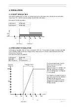
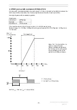
4.3 PWM ( pulse width modulated ) REGULATION 

At pulse width modulated regulation the relay outputs "on"-time is decided by the distance between the 
limit value and the actual value, the chosen proportional band and the chosen period time. 
 
Example at pulse width modulated regulation. 
 
Parameters: 
Limit value 1  

20

%

, high 

Xp-band 25 

Period time, T  

100 seconds 

 
The proportional band ( the XP-band ) is given in % of full measure range.  
Measure range = 0 - 100 

%

 = 100 

%

-units, which gives Xp-band 25% of 100 

%

-units = 25 

%

-units in 

our example. 


Relay "on" ( % of period time ) is 
given as a linear function 
between 20

%

 and 45

%

, where 

the "on"-time is 0% of the period 
time at 20

%

 and 100% of the 

period time at 45

%

 and above. 


NOTE ! t

min

 = 500 ms, t

max

= T minus 230 ms 


%

100%

50%

10

20

30

40

50

60

Proportional band

limit value 1

Relay “on”
in % of period time

T

t

on

off

T = Period time
t = Actual % av Period time

Summary of Contents for 1005RE

Page 1: ...1005RE ORP v1 1b Instructions...

Page 2: ...N AT ON OFF AND PWM REGULATION 5 2 6 EXAMPLE OF INSTALLATION AT FREQUENCY REGULATION 5 3 FUNCTIONS 6 3 1 COMMON FUNCTIONS 6 3 2 6 3 2 1 MEASURE 6 3 2 2 CAL 1 6 3 2 3 EXIT TO MEASURE 6 3 2 4 L1 6 3 2 5...

Page 3: ...n isolated output 0 4 20 mA proportional to the measured value for connection to for example a computer printer or other recording equipment When measuring is interrupted the output stays frozen at th...

Page 4: ...CONNECTIONS 2 3 1 Preparation Loosen the 4 plastic screws that hold the instrument front part at the same time as the front is kept on place with one hand Loosen carefully the front part and fasten t...

Page 5: ...ng Use a low noise coax cable between the electrode and the input terminal on the controller Low noise cables has in general a black semi conductive sheath between the centrewire insulation and the sh...

Page 6: ...ccording to the drawing to the left 2 6 EXAMPLE OF INSTALLATION AT FREQUENCY REGULATION Example connection of electromagnetic dosing pumps designed for 230 volts supply and pulse input E1 E1N1N1 L1 L1...

Page 7: ...ys frozen at the latest value the relays opens up and the regulation is paused until is pressed 3 2 3 2 1 MEASURE When power supply is connected the measuring mode starts 3 2 2 CAL 1 Offset calibratio...

Page 8: ...100 3 2 11 I TIME Integration time between 0 2000 seconds 3 2 12 ALARM The alarm relay delay can be set to 0 9999 seconds When an error occurs in the measuring mode the alarm diode activates at the s...

Page 9: ...1 at parameter setting mode FUNCTION 2 in measuring mode Steps down the menu Accelerating key Increase the value in setting mode Used when making a choice according to the display Interrupt measuring...

Page 10: ...er of pulses minute is decided by the distance between the limit value and the actual value the chosen proportional band and the chosen max frequency Example at frequency regulation Limit value 1 25 h...

Page 11: ...h modulated regulation Parameters Limit value 1 20 high Xp band 25 Period time T 100 seconds The proportional band the XP band is given in of full measure range Measure range 0 100 100 units which giv...

Page 12: ...on compared with P regulation The doubling is performed with an interval corresponding to the set I time until either the measured value is within the limits or that max frequency alt max on time is r...

Page 13: ...as to be set Turn the power supply on 5 2 1 Relay configuration When delivered the instrument is pre set for On Off regulation Limit value 1 is set to 100 min value LO limit value 2 is set to 100 min...

Page 14: ...irm 3 Decide the function shutdown at alarm shall be on Shon or off ShoF with Press to confirm 3 Step to EXIT TO MEASURE by pressing M repeatedly Press to start measuring 5 2 2c Proportional regulatio...

Page 15: ...ired set 0000 Use and Press to confirm 9 The diode at ALARM is activated the display shows 0300 Set the time delay in seconds use and Press to confirm 11 Decide if the function shutdown at alarm shall...

Page 16: ...the EXIT TO MEASURE diode is activated The display shows the actual measured value in the solution measured at the same time as the corresponding mA signal is sent to the output During the operation...

Page 17: ...sponding signal is sent to the output Press 04 00 is shown on display at the same time as the corresponding signal is sent to the output Press CH04 Test of the diodes All the menu diodes are activated...

Page 18: ...to measuring mode the measuring starts automatically 6 3 RESET OF DEFAULT SETTINGS The default settings are reset according to chapter 5 1 1 Turn the power supply off 2 Press and turn on the power su...

Page 19: ...ply 230 VAC 50 Hz Backup 10 years Range 0 100 Accuracy 0 1 Resolution 0 1 Offset Range 30 Calibration Offset 5 Input ORP inp z 10 12 Outputs Output 0 20 mA 4 20 mA Max load output 700 Alarm relay Pote...

Reviews: