ELKHART BRASS Copperhead RF 8593-04 Installation, Operating,  & Maintenance Instructions Download Page 4

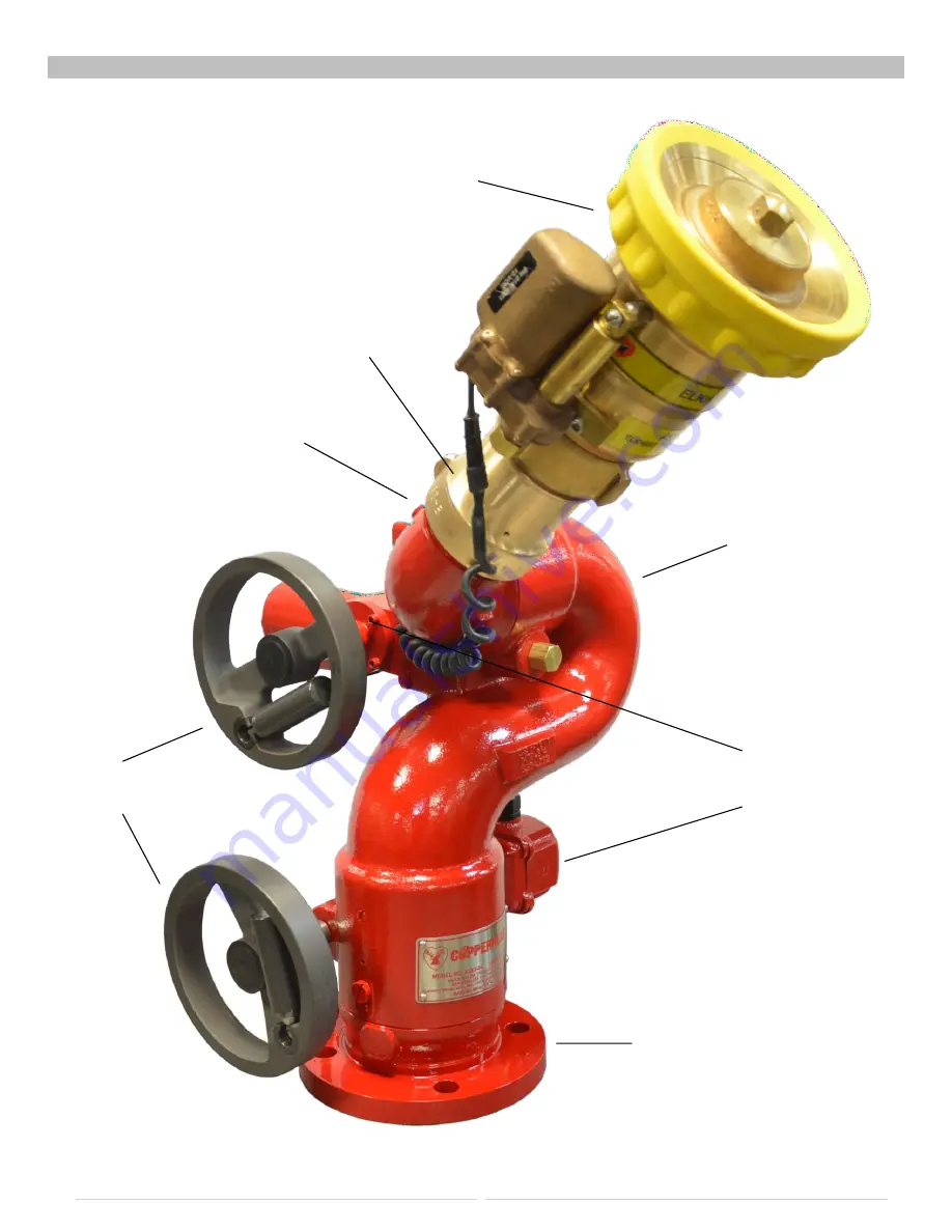
MONITOR CALLOUT DRAWING 


Optional SM-1250BE 

Electronically Actuated Nozzle 


282-B Stream Shaper 


2.5” NHT Discharge 


Fully Vaned Cast 

Brass Waterway 


Dual Handwheel 

Manual Override 

Sealed High- 

Torque Gearmotor 


3” 150# ANSI Flange 


8593-04 Copperhead RF Monitor 

Summary of Contents for Copperhead RF 8593-04

Page 1: ...2 8593 04 Monitor Installation Operating Maintenance Instructions 98520000 REV A 1 574 295 8330 www elkhartbrass com...

Page 2: ...lation Step 2 Communication Address Setup 10 Installation Step 3 RFSettingsSetup 11 Installation Step 4 System Programming 13 OPERATING INSTRUCTIONS 14 MAINTENANCE INSTRUCTIONS 16 SYSTEM SPECIFICATION...

Page 3: ...equipment should be operated from a remote location Do not needlessly expose personnel to dangerous fire conditions Open water valves supplying this equipment slowly so that piping fills slowly thus...

Page 4: ...ptional SM 1250BE Electronically Actuated Nozzle 282 B Stream Shaper 2 5 NHT Discharge Fully Vaned Cast Brass Waterway Dual Handwheel Manual Override Sealed High Torque Gearmotor 3 150 ANSI Flange 859...

Page 5: ...n All monitor motors are 12VDC If using a non Elkhart nozzle another 12VDC nozzle should be used or nozzle control may not function properly NOZZLE Copperhead RF Nozzles There are two nozzles recommen...

Page 6: ...equiring no wires between the RF transmitter and the monitor It is powered by the vehicle electrical system The faceplate is intended for a flush mount onto the pump panel Separate sealed push button...

Page 7: ...ace mount type switch box with controls for operation of the monitor for use with the OEM secondary RF transmitter Separate sealed toggle switches are furnished for up down left right and strt fog fun...

Page 8: ...Alignment is correct when the straight ahead position is centered between adjacent flange holes Attach monitor inlet flange to companion flange on water supply pipe with four 4 2 5 8 11 UNC grade 5 s...

Page 9: ...rtment and in a position that provides the least obstructed line of sight to the monitor s antenna Place a 1A fuse between the red lead of the RF controller and a switched positive power lead on the v...

Page 10: ...to a relay or LED supplied by the OEM The circuit switches in a ground and is limited to 250 mA of current when the monitor is in a non stowed position Installation Step 2 Communication Address An RF...

Page 11: ...and milled slot in the base Follow the programming steps to set all travel limits as prescribed in Installation Step 4 NOTE The horizontal limits must be set to stop the motors at the location of the...

Page 12: ...Programming Button The status LED will flash twice to acknowledge the new limit position To set the horizontal stow position of the monitor move the monitor left or right to the desired position Quick...

Page 13: ...ttons are pressed at the same time the monitor will stop all motion To continue motion release both buttons and repress the desired direction button This is also true for the up down and fog stream co...

Page 14: ...ts Serious damage to motor gear heads will occur Storing the Monitor Elkhart Brass recommends that a stow position be set and the stow routine be utilized to place the monitor in its stowed position a...

Page 15: ...r is exposed to a high level of radiant heat for a prolonged period it may be possible for the factory grease to thin and run out of the rotation joints In such an event fresh grease should be applied...

Page 16: ...Lithium batteries Replace the battery cover DS4 DS2 DS3 DS6 SW1 DS1 SW3 DS5 SW4 B P4 P1 P3 P2 A SW2 Reference Indication Meaning 1 Light comes on for 1 second when monitor stops Motor has reached stal...

Page 17: ...nts Without Converter Assembly 12VDC 11 14VDC WithConverter Assembly 11 30VDC at the controller under full load Electrical Load See Table 4 Below Control current 0 07 A 12V Operatingtemperaturerange 4...

Page 18: ...CHECK BEFORE DRILLING NOTE Pages must NOT be scaled during printing or template size will be scaled incorrectly Panel Mount Controller Mounting Template COMPONENT MOUNTING TEMPLATES IF YOU CAN SEE THI...

Page 19: ...ROM THE DIGITAL PDF DOUBLE CHECK BEFORE DRILLING Secondary Control Switch Box Mounting Template 0 24 2 HLS REQ D 4 92 4 45 0 281 DRILL THRU IF YOU CAN SEE THIS TEXT PLEASE REPRINT THIS PAGE AT 100 NOT...

Page 20: ...21 Auxiliary Battery Mounting Layout THIS IS NOT A TEMPLATE...

Page 21: ...DSLEY AVE P O BOX 1127 ELKHART IN 46514 PHONE 1 574 295 8330 1 800 346 0250 FAX 574 293 9914 WWW ELKHARTBRASS COM ELKHART BRASS MFG CO INC 2014 8593 04 MONITORS INSTALLATION OPERATION AND MAINTENANCE...

Reviews: