85
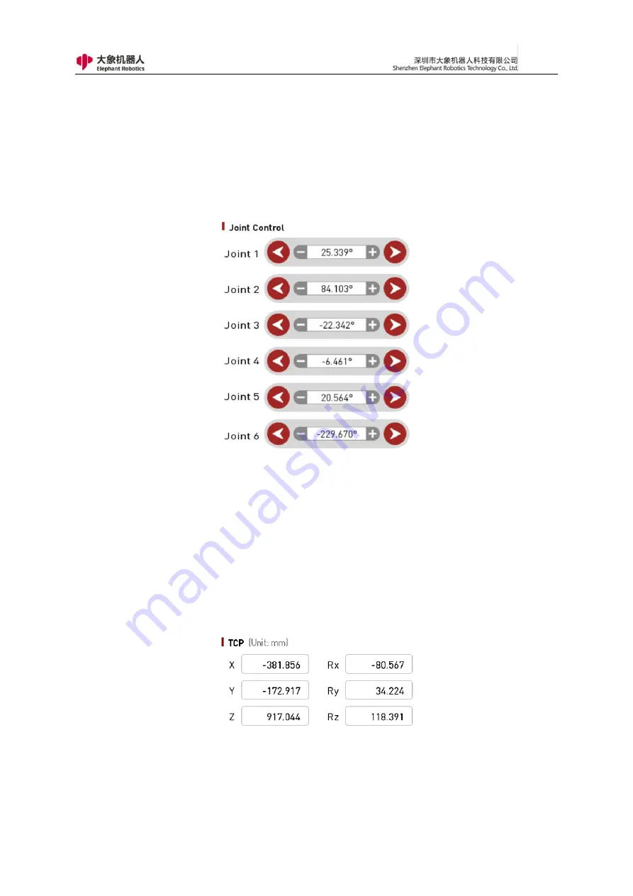
manipulate the robot and control the robot for joint movement using the
instructor. The control buttons for each joint are divided into 2 directions, and the
angle data of each axis can be seen.
Figure 3- 9 Joint motion mode control window
10
,
Coordinate position
As shown in Figure 3-10, this window displays the coordinate position
corresponding to the coordinate control.
Figure 3- 10 Coordinate position display window
11
,
Status display button: The button has two states, "OK" (displays green)
Summary of Contents for myCobot Pro 600
Page 1: ...1 Elephant Robotics User Manual myCobot Pro 600 Language English Compiled in 2022 3 28...
Page 27: ...27 Fig 2 9 State of Being Not Powered On...
Page 28: ...28 Fig 2 10 In the Process of Being Powered On Fig 2 11 Completion of Being Powered On...
Page 35: ...35...
Page 37: ...37 3 2 Product Appearance and Composition Fig 3 1 Product Composition...
Page 38: ...38 3 3 Working Principles and Specifications 3 3 1 Working Space...
Page 39: ...39 3 3 2 Coordinate System DH parameters and coordinate system Fig 3 2 DH Coordinate System...
Page 40: ...40 Fig 3 2 DH Coordinate Parameter...
Page 45: ...45 Fig 3 10 Size Parameters of End Mounting Hole...
Page 75: ...75 Figure 2 25 Language and unit 6 Time Figure 2 26 shows the time setting page...
Page 88: ...88 Figure 3 13 Network settings...
Page 95: ...95 Figure 3 21 Basic Settings...
Page 113: ...113 Figure 4 17 Subprogram Figure 4 18 Display subroutine...
Page 135: ...135 Fig 5 88 Connect to RoboFlow Fig 5 89 Connected Successfully...


