


Page 30
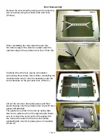
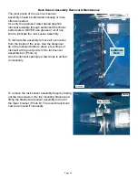
3.
Before the element can
be removed from the support
channel the locking tab on the
mounting clip must be closed
by squeezing shut with a pair
of pliers. After the repair is
complete the tab can be
reopened by using an awl or
similar instrument.
4.
Remove the mounting screw that secures the
element support channel to the cooktop.
5.
Carefully pull the support channel away from
the cooktop far enough to disengage the element
mounting clips from the channel. Slide the element
out from between the support channel and the
cooktop. Reinstall or replace the element by
reversing steps 1-5.
The element mounting clips must be removed
from the original element and mounted to the
replacement. The screw holes on the element
body are numbered to identify the clip mounting
locations.
Clip
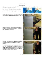
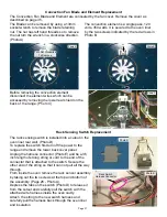
Surface Element Replacement
1
. Before removing the element be sure to note
the locations of the element mounting clips in the
support channel slot. The replacement element must
be installed in the same position.
2
.
Carefully remove the wires from the element.
Take note of the
terminal identification
on the
element terminal block for each wire connection.
Summary of Contents for CEI30EF5GB
Page 11: ...Page 11 Wiring Diagram Electric Wave Touch Models with Lower Oven ...
Page 12: ...Page 12 Schematic Diagram Electric WaveTouch Models with Lower Oven ...
Page 13: ...Page 13 Wiring Diagram Electric IQ Touch Models with Warming Drawer ...
Page 14: ...Page 14 Schematic Diagram Electric IQ Touch Models with Warming Drawer ...
Page 46: ...Page 46 ...
Page 47: ...Page 47 NOTES ...


