


installation
installation
LPG conversion -
DONG YANG regulator
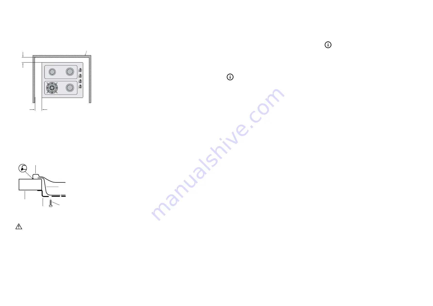
Figure 5
110mm
115mm
wall
4.
Fitting the cooktop into the bench.
Carry out as follows.
• Place the rubber seal provided around the edge of the hob.
NOTE: The rubber seal has talc powder applied to it’s
surface which should be wiped off with a damp cloth
after the unit has been installed.
Figure 6
hob
rubber seal
benchtop
screw
clamp
burner box
• Fit the pull-down clamps supplied to ensure that the
cooktop cannot move after installation.
WARNING
warning
Failure to fix the cooktop to the bench could result in loosening of
the gas connection through movement of the cooktop and a gas
leak may result.
• Use the 4 clamps and 4 screws supplied in the parts bag.
• To assemble, attach the 4 clamps to each corner of the
burner box via the screw provided.
• When placing the cooktop in the cut-out, swing the
clamps parallel with the box to avoid interference with the
cut-out.
• Position the cooktop so it is centred, then swing the
clamps under the benchtop and tighten.
Operation on NG/SNG
Regulator
An appliance regulator is provided. The regulator must be
positioned so that the pressure test nipple is accessible when
the appliance is installed. Connect the gas supply to the ½”
B.S.P. internal thread inlet of the regulator. Refer to ‘bench
cutout’ (Figure 4) for connection point position.
Regulators are supplied pre-adjusted and configured by the
component maker for use with Natural Gas. The appliance
installer is not required to make an adjustment to obtain the
correct outlet pressure setting.
An arrow on the base of the regulator indicates the direction
of gas flow when the inlet and outlet of the regulator is
oriented correctly. When the regulator has been fitted check
for leaks from the connections with soapy water.
Gas connection
This appliance is supplied for use with Natural Gas.
However, it can be converted for use with LPG. Refer to LP
conversion on pages 13-15.
Supply pipe sizing
The total hourly gas consumption for the appliance is shown
on the data label. The required supply pressure (i.e. at inlet
to appliance regulator) for each gas type is shown on the
data label, and given in Table 3. Use this information in
conjunction with the length of run, number of elbows, tees
and bends, the available service pressure and the supply
requirements of other installed appliances to determine
a suitable pipe size. For assistance in this matter refer to
the appropriate section of AS/NZS 5601.1 or
AS/NZS 5601.2.
An AGA certified class B or D flexible connection may be
used to connect the cooktop in accordance with AS/NZS
5601.1, in particular section 5.9 and clause 6.10.1.8, or
AS/NZS 5601.2, in particular section 2.11. Where a hose
assembly is used and the cooktop is in the installed position,
the hose assembly shall be suitable for connection to a fixed
consumer piping outlet located at a point 800 – 850mm
above the floor and in the region outside the width of the
appliance to a distance of 250mm. The point of connection
to consumer piping must be accessible with appliance
installed.
Elbow positioning
It is possible to reposition the elbow if required by loosening
the locking nut and elbow by using two spanners. Re-tighten
the entire assembly after the elbow has been repositioned.
When fitting elbow to appliance, ensure that the sealing
washer is fitted.
Checking the gas supply
1. Check the manometer zero point is correct.
2. Connect the manometer to the cooktop pressure point. This
is located on the regulator.
3. Turn on the gas supply and electricity and try to ignite
the gas.
TIPS & INFORMATION
tips & information
It will take additional time to light the gas for the first time as
air needs to be purged from the pipes.
4. With the appliance operating check the outlet pressure:
• when all burners of the appliance are operating
at maximum,
• when the smallest burner of the appliance
is operating at minimum.
Under these conditions the outlet pressure should not vary
from the nominal outlet pressure of 1.00kPa by more than
+/–0.20kPa.
If the regulator appears to not be performing satisfactorily,
then check the following points.
1. If the outlet pressure is consistently too low then the inlet
pressure may be too low and adjustment of an upstream
regulator may be needed, or an upstream regulator or
valve with insufficient flow capacity may be present in the
gas supply line. If this is suspected then it may be necessary
to repeat the checks whilst
measuring both the inlet and outlet pressure to determine
if the inlet pressure is in the range 1.13 – 5kPa.
2. Check that the regulator has been fitted to the gas supply
line in the correct orientation, the arrow on the base of the
body indicates the direction of gas flow.
Once these checks have been completed, if the regulator
still fails to perform in a satisfactory manner it should be
replaced.
TIPS & INFORMATION
tips & information
Refer to page 15 if you have been supplied with a
CHANT regulator.
This appliance is fitted with Natural Gas burner injectors.
Please follow the procedure below if a conversion to suit LP
gas is required.
The conversion kit contains appropriate LPG
injectors and 1 LPG sticker.
To convert to LPG
1. Remove the hotplate burners to access the hotplate
injectors. Replace the factory fitted NG injectors with the
appropriate injectors, as supplied (see Table 3).
2. Unscrew the hex nut from the regulator. The hex nut, brass
washer and nylon insert will disengage as
an assembly.
3. Unclip the nylon insert from the nut assembly by rotating the
insert ¼ turn, and pulling it free.
4. Turn over the insert, and clip back into position.
5. Refit the hex nut assembly to the regulator ensuring that it is fully
screwed down. The regulator is now set for connection to LP.
6. Turn on the gas supply and at each new connection check
for leaks using soapy water: each hotplate valve should be
turned on, one at a time, and the injector hole blanked off
for several seconds.
7. The operation of the regulator can be confirmed by
connecting a manometer to the pressure test point located
on the side of the regulator body adjacent to the outlet.
With the appliance operating check the outlet pressure
• when all burners of the appliance are operating
at maximum,
• when the smallest burner of the appliance is operating at
minimum.
Under these conditions the outlet pressure should not vary
from the nominal outlet pressure of 2.60kPa by more than
+/–0.52kPa.
8. If the regulator appears to not be performing satisfactorily
then check the following points.
• If the outlet pressure is consistently too low then the inlet
pressure may be too low and adjustment of an upstream
regulator may be needed, or an upstream regulator or
valve with insufficient flow capacity may be present in
the gas supply line. If this is suspected then it may be
necessary to repeat the checks whilst measuring both the
inlet and outlet pressure to determine if the inlet pressure
is in the range 2.75–7.00kPa.
• Check that the insert has been fitted correctly as per
diagram figure 7. Check that the hex nut is fully
screwed down.
12 USING YOUR COOKTOP Gas Cooktops
Gas Cooktops LP CONVERSION - DONG YANG 13


