01/2009 - Art. Nr. 4200 1016 3900A
21
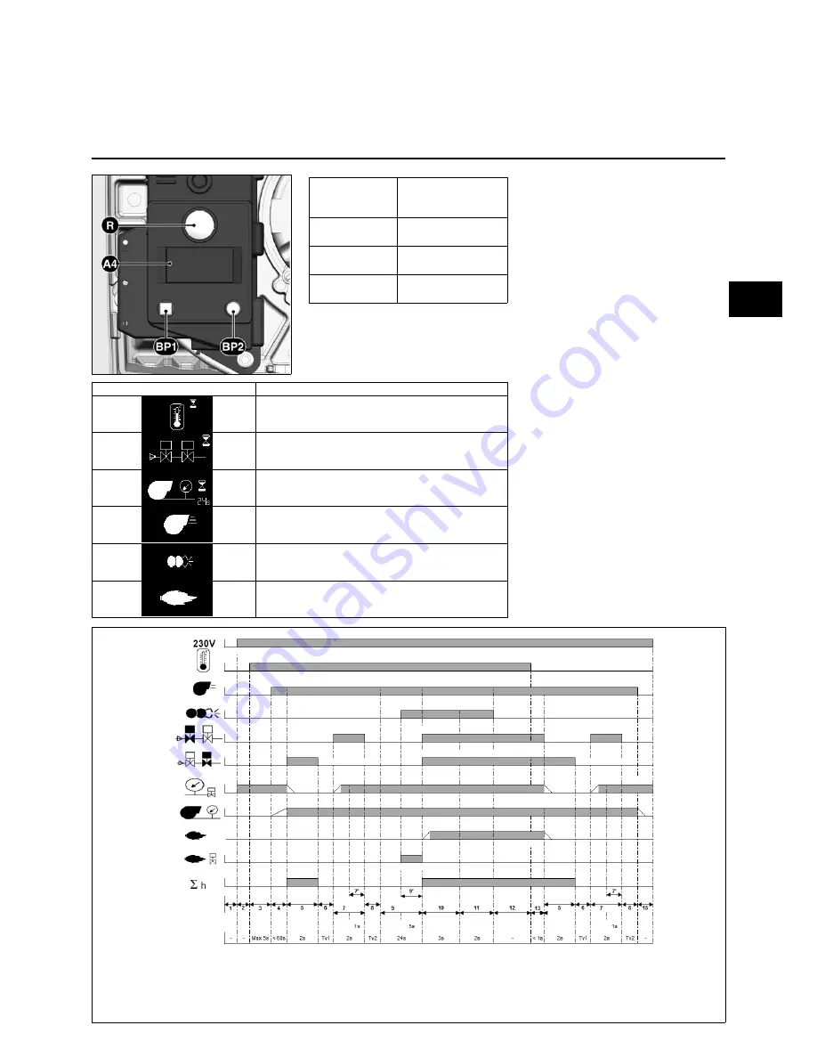
Function
Automatic control unit TCG 1xx
Pressing and
holding the
R
button for ...
... leads to ...
… 1 second...
Unlocking of the
control unit
... 2 seconds....
Locking of the
control unit
... 9 seconds.... Clearance of control
unit statistics
The TCG 1xx automatic gas combustion
control unit controls and monitors the forced-
draught burner. The microprocessor-
controlled programme sequence ensures
maximum stability of time periods, regardless
of fluctuations in the power supply or ambient
temperature. The automatic combustion
control unit is designed to cope with
brownouts, guaranteeing system operation
even in the event of extreme power failures.
Whenever the supply voltage drops below its
rated minimum level, the control unit shuts
down - even in the absence of a malfunction
signal. The control unit switches itself back on
again once the voltage has returned to
normal levels.
Locking and unlocking the system
The control unit can be locked (switched to
malfunction) and unlocked (malfunction
cleared) by pressing the
R
reset button,
provided the system is connected to the
mains power supply.
Always disconnect the power supply
before installing or removing the
control unit. Do not attempt to open or
carry out repairs on the control unit.
A4
display
BP1
push-button 1
Request: fault code
BP2
push-button 2
Request: values
Symbol
Designation
Waiting for heat request
Valve leak check
(by gas pressure measurement in valve space)
Waiting for air pressure switch during burner start
Burner motor on
Ignition transformer on
Flame present
Functional sequence phases:
1: No voltage
2: Power supply on, no heat request
3: Heat request, check air pressure switch
idle position
4: Motor on, check air pressure
5: First phase: sealing test
6: Test time 1 (valve space depressurised)
7: Second phase - valve check
8: Test time 2 (valve space filled)
9: Preventilation
9: Pre-ignition, activation of unauthorised
flame monitoring
10: Flame formation, safety period
11: Post-ignition time
12: Operation
13: Burner stop
14: Standby
en
en