47
7.3
CONTROL PANEL MOUNTING
7.3.1
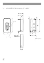
CUTOUT
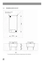
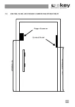
To install the ekey
®
TOCAhome integra control panel, prepare a cutout according to the
figure on page 45.
7.3.2
WIRING
When installing the cables, please take care to have enough cable buffer left to plug the
device in and out, so that you can still build the device in.
7.3.3
ELECTRIC CONNECTION
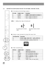
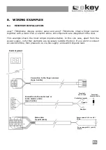
The control panel is powered by the white and brown wire of the 8-pole main cable X1.
For DC power supply, please connect the white cable to the positive (+) pole and the
brown cable to the negative (-) pole. When using AC power supply, you need to connect
the brown as well as the white cable to the AC adapter.
The power source capability should be defined so that there is enough power both for
ekey
®
TOCAhome integra (approx. 1W) and the consumer load at relay 1 (X6).
For instance: motor lock 24VDC 1A + ekey
®
TOCAhome integra at 24VDC approx.
100mA. Power supply should be in this case at least 27 Watt, so 24VDC 1,1A.
The power supply for the motor lock (optional) is taken directly from the control panel
(3-pole X6 screw terminal).
7.3.4
CONNECTING A MOTOR LOCK
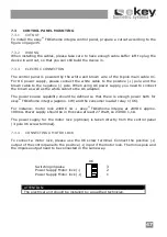
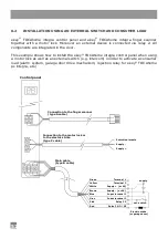
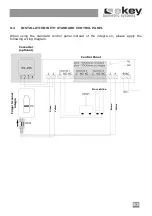
To connect a motor lock, please use the X6 screw terminal. Connect the positive (+)
output of the control panel to the positive (+) input if the motor lock. The minus pole and
the impulse output need to be connected in the same way.
ATTENTION:
The electrical unit should be installed by a qualified technician.
Switching impulse
3
Power Supply Motor lock (-)
2
Power Supply Motor lock (+)
1
X6
Summary of Contents for TOCAhome 2 integra
Page 11: ...11 ...
Page 16: ...16 6 2 ABMESSUNGEN DER STEUEREINHEIT INTEGRA ...
Page 17: ...17 6 3 ABMESSUNGEN DES FINGERSCANNER INTEGRA ...
Page 19: ...19 7 2 AUSFRÄSUNG FINGERSCANNER empfohlene Fräsmasse können je nach Werkstoff variieren ...
Page 28: ...28 ...
Page 38: ...38 ...
Page 43: ...43 6 2 DIMENSIONS OF THE INTEGRA CONTROL PANEL Shield width ...
Page 54: ...54 ...


