background image


34 


3.4


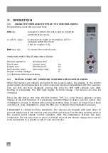
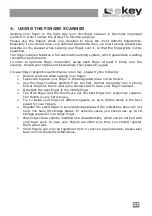
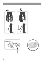
RECORDING A FINGER WITH THE SENSOR (SEE PAGE 38) 

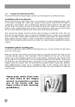
It is important that the user draws his/her finger correctly across the sensor. 
 

The  best  results  are  achieved  by  using  the  middle  finger  while  the  index 
and ring finger stabilize the middle finger. 

 
Place the entire surface of the desired finger 

after the last joint

 onto the sensor. 

The larger the surface area of the finger, the higher the probability will be that the finger 
is recognised by the device the next time it is placed on the sensor. 
 
In  order  to  obtain  the  best  possible  recognition  performance  from  the  system,  please 
always swipe your finger over the sensor in the same way you did it when enrolling your 
finger. 
 
The  sensor  is  located  in  the  middle  of  the  finger  mould  (see  figure  on  page  31).  Swipe 
your finger gently (not too hard and not too soft) and at average speed over the sensor. 
 
People  who  do  a  lot  of  manual  work  are  requested  to  pay  attention  to  the  wear  off  of 
their  finger  lines,  i.e.  a  right-handed  person  should  record  fingers  from  their  left  hand 
and vice versa. 
If you notice that your fingerprints are not so visible, when looking at your fingers with 
your bare eyes, please choose the fingers which have the best available fingerprints. 
 

ATTENTION: 

Please swipe the largest possible finger surface, starting from the first finger joint and 
applying gentle pressure. The larger the scanned finger surface, the easier it will be for 
the finger to be recognised. 


3.5


HOW TO ENROL A FINGER 

You may enrol up to 99 fingers 
 

3.5.1


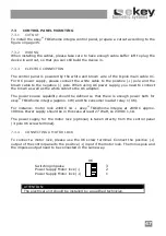
ENTERING THE SECURITY CODE 


Press the OK-key in the control panel. 


Enter the first digit of the security code using < and > (standard setting is 9) 


Press the OK-key. 


Enter the second digit of the security code using < and > (standard setting is 9) 


Press the OK-key. 


In the display “Eu” (enrol user) is visible. 


3.5.2


SETTING ACCESS RIGHTS 


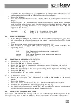
If “Eu” is visible in the display of the control panel, press the OK-key. 


Setting user number: The display shows “1“. If the user ID is already taken, a 
red  dot  appears  in  the  lower  right  hand  corner  of  the  display.  Example:  “1.” 
Select a free user ID by using the < and > keys. 


Press the OK-key. 


Setting  finger  number:  The  display  shows  “F1”.  F1  stands  for  finger  1.  Start 
counting  your  fingers  from  the  little  finger  of  the  left  hand.  The  little  finger  of 
your right hand would then be number 10 (setting “F0” in the display) e.g. “F7” 

Summary of Contents for TOCAhome 2 integra

Page 1: ...BEDIENUNGSANLEITUNG OPERATING INSTRUCTIONS ekey TOCAhome integra ekey TOCAhome 2 integra ekey TOCAhome pc integra Zutrittsystem mit Fingerscan Fingerscan Access Control System ...

Page 2: ...en Wir wünschen Ihnen viel Freude mit Ihrem Produkt Besuchen Sie die Webseite von ekey biometric systems GmbH unter www ekey net Dort finden Sie stets die aktuellste Version dieses Dokuments sowie weitere zusätzliche Informationen über dieses und andere Produkte von ekey biometric systems Sollten Sie noch offene Fragen haben so wenden Sie sich bitte an unseren Support unter der Nummer 43 732 6910 ...

Page 3: ... FINGERSCANNERS 10 5 FEHLERBESCHREIBUNG 12 6 TECHNISCHE DATEN 14 6 1 STECKERBELEGUNG DER STEUEREINHEIT INTEGRA 15 6 2 ABMESSUNGEN DER STEUEREINHEIT INTEGRA 16 6 3 ABMESSUNGEN DES FINGERSCANNER INTEGRA 17 7 MONTAGE UND INSTALLATION 18 7 1 AUSFRÄSUNG STEUEREINHEIT 18 7 2 AUSFRÄSUNG FINGERSCANNER 19 7 3 MONTAGE DER STEUEREINHEIT 20 7 4 MONTAGE DES FINGERSCANNERS 21 7 5 MONTAGEHÖHE FÜR STEUEREINHEIT U...

Page 4: ...hloss anzusteuern Vorzugsweise ist dies bei Verkabelung in der Tür das Relais 1 Mittels eines externen Eingangs lässt sich Relais 1 über einen externen Taster fernbedienen und eine Fernöffnung beispielsweise über eine Sprechanlage oder ähnliches realisieren Voraussetzung dafür ist ein potentialfreier Schalter 2 LIEFERUMFANG Die ekey TOCAhome integra Steuereinheit und der ekey TOCAhome integra Fing...

Page 5: ...ieser Zeit leuchtet die Statusanzeige am Fingerscanner rot Nachdem der Startvorgang abgeschlossen ist beginnt die Statusanzeige orange zu blinken Nun kann die Initialisierung gestartet werden Betätigen Sie bitte die OK Taste und im Anschluss die ESC Taste Am Display erscheint EF für Enroll Finger Nun kann ein bereits aufgenommener Finger über den Sensor gezogen werden und der Initialisierungsvorga...

Page 6: ...ts Eu Aufnahme neuer Finger rr Rücksetzen auf Werkseinstellung Sc Einstellen Sicherheitscode du Benutzer löschen 0 99 Eingabe Sicherheitscode 0 99 Eingabe neuer Sicherheitscode 1 99 Benutzer Nr auswählen 1 99 Benutzer Nr auswählen F1 F9 F0 Finger Nr auswählen 01 02 Relais auswählen 0 99 Eingabe Sicherheitscode blinkender Punkt Normalbetrieb Siehe Abschnitt 3 5 Siehe Abschnitt 3 7 Siehe Abschnitt 3...

Page 7: ...em Fall Finger der linken Hand einspeichern Sollten Sie bei Ihren Fingern erkennen dass die Fingerlinien mit dem freien Auge schlecht erkennbar sind so verwenden Sie bitte die Finger bei denen die Fingerlinien am schönsten ausgeprägt sind ACHTUNG Bitte versuchen Sie eine größtmögliche Fläche Ihres Fingers ab dem vorderen Gelenk mit wenig Druck über den Sensor zu ziehen Damit erreichen Sie die höch...

Page 8: ...ais 1 typ Motorschloss o2 Relais 2 nur bei ekey TOCAhome 2 integra 3 6 AUFNAHME DES FINGERS Nach Erscheinen der Anzeige EF haben Sie nun 60 Sekunden Zeit Ihren Finger ab dem vorderen Gelenk über den Sensor zu ziehen Die Aufnahme sollte in der in Abschnitt 3 4 beschriebenen Art und Weise geschehen Der Fingerscanner besitzt eine Statusanzeige LED die in drei verschiedenen Farben den Zustand signalis...

Page 9: ...et Eu Enroll user 3 8 2 DURCHFÜHRUNG DER NEUEINSTELLUNG Drücken Sie so oft auf die Taste bis Sc angezeigt wird Drücken Sie die OK Taste Geben Sie mit den und Tasten die linke Ziffer des neuen Securitycodes ein Drücken Sie die OK Taste Geben Sie mit den und Tasten die rechte Ziffer des neuen Securitycodes ein Drücken Sie die OK Taste Es erscheint kurz die Anzeige Ok Das Gerät geht danach in den Nor...

Page 10: ...destens 5 mal über den Sensor Sollten Sie Ablehnungen haben so wiederholen Sie bitte diesen Vorgang Sollten Sie keine ausreichende Fingererkennungsleistung haben versuchen Sie diese Hinweise Verringern Sie den Druck beim Ziehen des Fingers Achten Sie darauf dass sie genau innerhalb des im Gehäuse sichtbaren Fingerbereichs ihren Fingerzug starten Die Fingerfläche ab dem vorderen Gelenk verwenden Fa...

Page 11: ...11 ...

Page 12: ...nungsgemäß durchgeführt 3 Der Finger wird falsch über den Sensor gezogen 1 Finger erneut einlernen und immer gleichmäßig über den Sensor ziehen 2 Siehe Das Aufnehmen eines Fingers funktioniert nicht perfekte Aufnahme garantiert gute Erkennungs leistung 3 siehe Seite 11 Statuspunkt der Steuereinheit blinkt nicht Keine Versorgungsspannung 1 Spannungsversorgung Sicherstellen eventuell Sicherung überp...

Page 13: ...nnung des Fingers aber das Relais schaltet nicht Falsche Gerätezuordnung Die Erkennung wird nicht akzeptiert da eines der Geräte getauscht wurde Kopplung neu durchführen an einem der Geräte wurde manipuliert Gerät vor der Kopplung auf Werkszustand zurücksetzen siehe 3 9 Am Fingerscanner blinkt abwechselnd die grüne und rote Statusanzeige Mögliche Probleme oder Beschädigung des Sensor Setzen Sie si...

Page 14: ...t nach Stromausfall SICHERHEIT Gerätekopplung zwischen Steuereinheit und Fingerscanner niedrige Falscherkennungsrate FAR 1x10 6 bei FRR 1 4x10 2 ELEKTRISCHE EIGENSCHAFTEN Eingangsspannung 8V 24V AC 8V 30V DC Leistungsaufnahme ca 1W ohne Motorschloss Schaltleistung Relais 30V 2A Leistung Motorschloss 30V 2A UMGEBUNGSBEDINGUNGEN Temperaturbereich 40 C 85 C Schutzklasse Steuereinheit IP41 im eingebau...

Page 15: ...er NC Werkseinstellung X6 Schraubklemme Relais 1 typisch Motorschloss Klemme Nr Funktion 1 Versorgung Motorschloss gleich X1 weiss 2 Versorgung Motorschloss gleich X1 braun 3 Schaltimpuls geschalten X1 weiss X1 Hauptzuleitung Pin Nr Kabelfarbe Funktion 1 Blau Schalteingang Anschluss 1 2 Grau Schalteingang Anschluss 2 3 Gelb ekey TOCAhome Klemme 2 4 Grün ekey TOCAhome Klemme 1 5 Braun Versorgungssp...

Page 16: ...16 6 2 ABMESSUNGEN DER STEUEREINHEIT INTEGRA ...

Page 17: ...17 6 3 ABMESSUNGEN DES FINGERSCANNER INTEGRA ...

Page 18: ...ung die Position der Ausnehmung ist frei wählbar Türblatt Bohrungen f Befestigungsschrauben optional min 8mm 7 MONTAGE UND INSTALLATION 7 1 AUSFRÄSUNG STEUEREINHEIT Auslass für Kabelzuführung X1 X3 X6 von Fingerscanner Motorschloss und Hauptzuleitung Die Position der Ausnehmung ist frei wählbar min 15mm Die Fräsbreite ist Modellabhängig und beträgt 18mm 20mm oder 24mm 234 00mm ...

Page 19: ...19 7 2 AUSFRÄSUNG FINGERSCANNER empfohlene Fräsmasse können je nach Werkstoff variieren ...

Page 20: ... weiße Ader mit dem Wechselspannungsnetzteil Die Dimension der Spannungsversorgung ist so zu wählen dass diese genug Leistung für den Betrieb von ekey TOCAhome Integra 1W und den angeschlossenen Verbraucher an Relais 1 X6 hat Beispiel Motorschloss 24VDC 1A plus ekey TOCAhome integra bei 24VDC ca 100mA Die Stromversorgung sollte in diesem Fall mindestens 27 Watt also 24VDC 1 1A sein Die Versorgungs...

Page 21: ... Türblatt sicherzustellen Montieren sie das mitgelieferte Dekorelement erst nach vollständiger Inbetriebnahme Einbau ohne Montagedübel Für den Einbau ohne Montagedübel z B in einen Türrahmen müssen die am Gehäuse angebrachten Dübel abgeschnitten werden Fräsen Sie eine Ausnehmung lt Abbildung auf Seit 19 aus und bohren Sie zwei Löcher für die Befestigungsschrauben Durchmesser ca 2mm Verlegen Sie da...

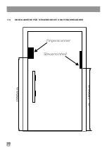
Page 22: ...22 1550m m c a 1 300m m Fingerscanner Steuereinheit 7 5 MONTAGEHÖHE FÜR STEUEREINHEIT UND FINGERSCANNER ...

Page 23: ...Dekorelement vorsichtig aus dem Rahmen indem Sie am unteren oder oberen Gehäuserand zwischen das Dekorelement stoffrand ansetzen 23 Um das Dekorelement zu montieren nehmen Sie dieses seitlich mit zwei Finger und setzen es in den unteren Rand des Gehäuses ein so dass die unteren Befestigungslaschen in die dafür vorgesehenen Ausnehmungen Anschließend üben Sie leichten k auf die obere Kante des eleme...

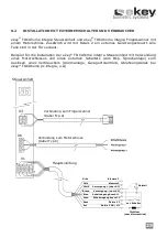
Page 24: ...i werden außer der Spannungs versorgung keine Elemente außerhalb der Tür benötigt Wird ein Türöffner angeschlossen so erfolgt dies über die Leitung Versorgung und Schaltimpuls Versorgung DC oder AC Weiß Versorgung DC oder AC Braun Steuereinheit Verbindung zum Fingerscanner Kabel Typ A Verbindung zum Motorschloss oder Türöffner Kabel Typ C Schaltimpuls Versorgung Versorgung Anschluss Türöffner Ansc...

Page 25: ...erwendung eines Motorschlosses und eines externen Schalters zum Bsp Sprechanlage zum Auslösen eines Verbrauchers Alarmanlage Garagentorantrieb Ablehnungsrelais bei ekey TOCAhome pc integra o ä Steuereinheit Verbindung zum Fingerscanner Kabel Typ A ext Schalter Gelb Klemme 2 Weiß Versorgung oder AC Braun Versorgung oder AC Blau Schalteingang Anschl 1 Grau Schalteingang Anschl 2 Rosa Relais 2 C Rot ...

Page 26: ...TEUEREINHEIT Bei Verwendung der Aufputzvariante der Steuereinheit anstatt der Steuereinheit Integra ist folgender Verdrahtungsplan anzuwenden Grün Gelb Braun Weiß Steuereinheit Aufputz Fingerscanner integra Konverter optional Türöffner ...

Page 27: ... weshalb der Abschluss einer entsprechenden Transportversicherung empfohlen wird ekey übernimmt keinerlei Haftung für Transportschäden durch unsachgemäße oder unzureichende Verpackung Keine Garantieansprüche bestehen für Produkte die 1 durch zweckentfremdete Verwendung Nichtbeachtung von Benutzerhinweisen in der zusammen mit dem Produkt gelieferten Bedienungsanleitung und oder Garantiekarte oder d...

Page 28: ...28 ...

Page 29: ...eys during your holiday Enjoy your new product Visit the official ekey biometric systems website at WWW EKEY NET There you will find up to date hints FAQs and the most current version of this document as well as additional information on this and other products by ekey biometric systems Should you have any further questions please call our support number at 43 732 6910 4552 Our entire team will be...

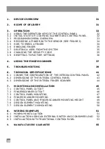
Page 30: ...UBLESHOOTING 39 6 TECHNICAL SPECIFICATIONS 41 6 1 CONNECTOR CONFIGURATION OF THE INTEGRA CONTROL PANEL 42 6 2 DIMENSIONS OF THE INTEGRA CONTROL PANEL 43 6 3 DIMENSIONS OF THE INTEGRA FINGER SCANNER 44 7 MOUNTING AND INSTALLATION 45 7 1 CONTROL PANEL CUTOUT 45 7 2 FINGERSCANNER CUTOUT 46 7 3 CONTROL PANEL MOUNTING 47 7 4 FINGER SCANNER MOUNTING 48 7 5 CONTROL PANEL AND FINGER SCANNER MOUNTING HEIGH...

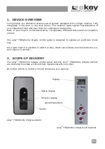
Page 31: ...e ekey TOCAhome integra control panel is designed to operate an electronic motor lock Via a gate input it is possible to switch a relay which can activate an external device i e door opener or similar 2 SCOPE OF DELIVERY The ekey TOCAhome integra control panel and the ekey TOCAhome integra scanner are delivered mounted wired and fully operational with your door No further efforts to install or mou...

Page 32: ... with the scanner Two red dots are then displayed During this time the LED light remains red After booting is completed the LED light begins to blink orange The device can now be initialised Press the OK button and then the ESC button EF i e enrol finger appears on the display of the control panel If a previously recorded finger is drawn over the sensor the initialisation process is started withou...

Page 33: ...c du 0 99 0 99 1 99 1 99 F1 F9 F0 01 02 Enter relay 0 99 Enter security code red blinking dot Normal operation Delete user Change security code Reset to initial factory setting Reset to initial factory setting Set finger number Select user number Enter now security code Enter the security code Continue chapter 3 5 Continue chapter 3 7 Continue chapter 3 8 Continue chapter 3 9 ...

Page 34: ...ur fingerprints are not so visible when looking at your fingers with your bare eyes please choose the fingers which have the best available fingerprints ATTENTION Please swipe the largest possible finger surface starting from the first finger joint and applying gentle pressure The larger the scanned finger surface the easier it will be for the finger to be recognised 3 5 HOW TO ENROL A FINGER You ...

Page 35: ...tes the operating mode Red The finger could not be scanned successfully please try again Orange The device is waiting for a finger to be scanned Green Successful scan 3 7 DELETING A USER FROM THE SYSTEM 3 7 1 ENTERING THE SECURITY CODE Press the OK key in the control panel Enter the first digit of the security code using and standard setting is 9 Press the OK key Enter the second digit of the secu...

Page 36: ...ng the system to the initial factory settings all data from the system is deleted The security code is reset to the factory default 99 and the scanner and control panel loose their coupling 3 9 1 ENTERING THE CURRENT SECURITY CODE Press the OK key in the control panel Enter the first digit of the security code using and standard setting is 9 Press the OK key Enter the second digit of the security ...

Page 37: ...ssure when swiping your finger Take care to place your finger in the designated place on the device Use the finger surface starting from the first Almost everybody has a strong fold at the joint this is where you should start to have your finger scanned Generally the best finger is the middle finger The little finger and the thumb are not the best fingers for ergonomic reasons The thumb is very ha...

Page 38: ...38 ...

Page 39: ...y 3 The finger is not being swiped correctly over the scanner 1 The finger has to be enroled again by swiping it consistently over the sensor 2 See I am unable to enrol a finger perfect enrolment ensures high identification rates 3 See page 37 Status point of the control panel is not blinking System not connected to the power supply 1 Ensure power supply check the glass tube fuse Two blinking dots...

Page 40: ...e scanner is signalling a positive identification however the relay is not released Wrong unit coupling The finger is not accepted as a device has been swapped Couple the devices again one of them has been manipulated Reset the device before coupling it see 3 9 Status LEDs blink green and red in the finger scanner Possible problem or damage on the sensor Contact our support department Take care th...

Page 41: ...data after power failure SECURITY Coupling between scanner and control panel Extremely low rate of false identification FAR 1x 10 6 for FRR 1 4x10 2 ELECTRICAL DATA Input voltage 8V 24V AC 8V 30V DC Input capacity 1W without motor lock Switching capacity 30V 2A Motor lock capacity 30V 2A AMBIENT CONDITIONS Temperature range 40 C 85 C Protection category Control panel IP41 when mounted Finger scann...

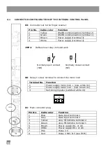
Page 42: ...ormally closed contact NO NC X6 Relay 1 screw terminal to connect the motor lock Terminal No Function 1 Power supply motor lock equ white X1 2 Power supply motor lock equ brown X1 3 Switching impulse switched white X1 X1 Main connector plug Pin No Cable color Function 1 Blue Gate input terminal 1 2 Grey Gate input terminal 2 3 Yellow ekey TOCAhome terminal 2 4 Green ekey TOCAhome terminal 1 5 Brow...

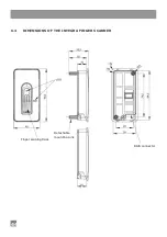
Page 43: ...43 6 2 DIMENSIONS OF THE INTEGRA CONTROL PANEL Shield width ...

Page 44: ...44 6 3 DIMENSIONS OF THE INTEGRA FINGER SCANNER Finger swiping track Detachable mounting pins RJ45 connector ...

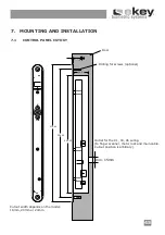
Page 45: ...snehmung ist frei wählbar Türblatt Bohrungen f Befestigungsschrauben optional min 8mm 7 MOUNTING AND INSTALLATION 7 1 CONTROL PANEL CUTOUT Outlet for the X1 X3 X6 wiring to finger scanner motor lock and main cable Cutout position is arbitrary Die Fräsbreite ist Modellabhängig und beträgt 18mm 20mm oder 24mm Door Drilling for screws optional Cutout width depends on the model 18mm 20mm or 24mm min 1...

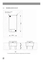
Page 46: ...46 7 2 FINGERSCANNER CUTOUT 5mm angle or radius at all 4 angles recommended milling dimensions depending on the material Type 1 mounting pin Type 2 screws Connector outlet ...

Page 47: ...e AC adapter The power source capability should be defined so that there is enough power both for ekey TOCAhome integra approx 1W and the consumer load at relay 1 X6 For instance motor lock 24VDC 1A ekey TOCAhome integra at 24VDC approx 100mA Power supply should be in this case at least 27 Watt so 24VDC 1 1A The power supply for the motor lock optional is taken directly from the control panel 3 po...

Page 48: ...order to guarantee a fixed hold of the integra scanner Mount the provided design element only after you have finished installing the whole system Installation without mounting pins In order to install the scanner without mounting pins e g in a door frame the pins have to be cut off the case Make an opening in the frame refer to the figure on page 46 and drill two holes for the mounting screws appr...

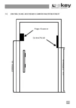
Page 49: ...49 1550m m ca 1300m m Fingerscanner Steuereinheit 7 5 CONTROL PANEL AND FINGER SCANNER MOUNTING HEIGHT Finger Scanner Control Panel ...

Page 50: ...the upper or the lower edge of the plastic housing and the design element Installing the design element is done by snapping it over the integra finger scanner as follows using two fingers grab the design element on the sides from the middle Align and insert the design element bottom two notches in the scanner two bottom holes While the bottom edge of the design element is in this position apply li...

Page 51: ...one case apart from the power supply no further elements are necessary outside the door If you wish to connect an electric strike then please do so via the supply and switch impulse lead Control panel Connection to the finger scanner type A cable Connection to the motor lock or to the electric strike type C cable Main cable type B cable Power supply DC or AC white Switching impuls Supply Supply Te...

Page 52: ...lock as well as an external switch e g intercom in order to activate a consumer load alarm system garage door drive mechanism rejection relay for ekey TOCAhome pc integra etc Control panel Connection to the finger scanner type A cable Connection to the motor lock or to the electric strike type C cable Switching impuls Supply Supply Main cable type B cable Yellow Terminal 2 White Supply or AC Brown...

Page 53: ...TH STANDARD CONTROL PANEL When using the standard control panel instead of the integra on please apply the following wiring diagram Green Yellow Brown White Control Panel Finger Scanner integra Converter optional Door strike ...

Page 54: ...54 ...
Page 55: ...ncluding appropriate insurance is recommended ekey assumes no liability for transport damages resulting from inappropriate or insufficient packaging No guarantee claims can be accepted for products that were damaged or made unable to operate 1 by using the product for a purpose for which they were not intended non observance of the notes for the user contained in the Instructions for Use and or in...

Page 56: ... systems GmbH Lunzerstraße 64 A 4030 Linz www ekey net Optische und technische Änderungen Satz und Druckfehler vorbehalten 800733 0738 Subject to optical and technical modifications any liability for misprints excluded ...

Reviews: