background image

UPS:  OFFICE 400 - 2000 


Device Description 


OFFICE Series


18 


3. 

UPS device description 

Sensitive loads require comprehensive protection against supply disruption. 
This includes: temporary mains failure, mains voltage fluctuations, mains volt-
age peaks, frequency changes, etc.  The uninterruptible power supply unit is in-
tended to support mains-supplied, sensitive electronic devices such as: comput-
ers, workstations, cash registers, operation-critical instruments, telecommunica-
tion devices, process control systems, etc. against supply disruptions. In doing 
so, the UPS supervises the above mentioned network sizes and supports the 
loads in critical moments. The support time, or autonomous duration, is depend-
ent on the size of the installed or adapted energy storage (accumulator).  


3.1 

Topology and operation modes 

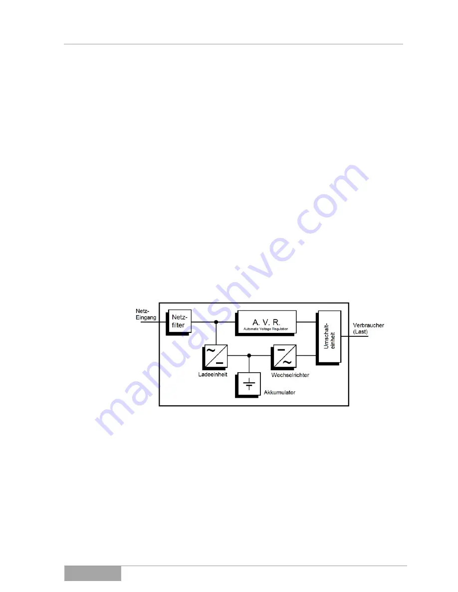
In the OFFICE series, there is a so-called 

“LINE INTERACTIVE” or “OFFLINE” 

setting. This is identified in that the load is directly supplied by the mains power 
supply in standard mode (

Mains operation

) (see Fig. 3-1). Light mains voltage 

fluctuations are then equalized by the AVR (AUTOMATIC VOLTAGE REGULA-
TION) so that a load operation is ensured to always remain in the standard 
mains voltage range.  


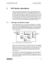
Fig. 3-1  Block diagram or setup of the OFFICE series. 


In the event of a massive mains fault, the switching unit turns on in the 

Inverter 

mode

 (Inverter operation or autonomous mode). The loads will only be operated 

directly via the inverter for the duration of the fault. The inverter draws the nec-
essary power from the accumulator during this autonomous period. Once the 
mains fault / mains failure has passed, the switching unit switches again to 
mains operation.  

As long as the device it connected to the mains power supply, the charging unit 
of the accumulator is being charged (

Charging mode

). The maximal autono-

mous duration for the UPS is dependent on both the charging status and the ca-
pacity of the accumulator. Please see the section on technical data in this oper-
ating manual for details. 

Summary of Contents for ACX11OFS1K000000

Page 1: ...Versions Article Numbers ACX11OFS40000000 ACX11OFS40000RS0 ACX11OFS60000000 ACX11OFS60000RS0 ACX11OFS80000000 ACX11OFS80000RS0 ACX11OFS1K000000 ACX11OFS1K000RS0 ACX11OFS1K500000 ACX11OFS1K500RS0 ACX11...

Page 2: ...it be used without authorization for competitive purposes or given made accessible to third parties The publication and copyright of this documentation are retained by EFFEKTA Regeltechnik GmbH Rheinw...

Page 3: ...Positioning 14 2 7 Connection 14 2 8 Operation 15 2 9 Working with accumulators 16 2 10 Maintenance service and malfunctions 16 3 UPS device description 18 3 1 Topology and operation modes 18 3 2 UPS...

Page 4: ...the support time autonomous time 38 12 2 Replacing components accumulators 39 12 3 Maintenance and service contracts 39 13 Technical Data 42 14 Scope of delivery Accessories 44 15 Optional accessorie...

Page 5: ...All na tional and local provisions and regulations for electrical installations have to be adhered to in the installation process The same applies to the operation of the device The content of this o...

Page 6: ...nual on to any subsequent users of the product 1 4 Abbreviations Terms and Symbols In this manual the abbreviation UPS stands for uninterruptible power supply Typically accumulators are used as energy...

Page 7: ...easures are not taken these dangerous situations can lead to slight or medium reversible injuries Text that is marked with ATTENTION contains very important instructions for situations that if acciden...

Page 8: ...te of the provided documentation and or instructions Disconnect before working Environmental Symbols Identifies instructions for recycling Identifies components that are subject to the Electronic Scra...

Page 9: ...r this infor mation is added at the end of the cross reference Example Fig 4 4 Pos 1 This means see in this manual in Chapter 4 in Figure 4 the position number 1 3 Numbers in brackets refer to the pos...

Page 10: ...repair by third parties in the event of changes unauthorized intervention improper oper ation false installation or other modifications not approved by us in the case of improper use such as the conn...

Page 11: ...1 7 Limitation of Liability Claims to damage compensation are excluded unless they involve intent or gross negligence by EFFEKTA Regeltechnik GmbH or its employees This does not affect liability acco...

Page 12: ...ign to provide a primary energy source for electrical devices and a short term supply from a secondary energy source for electrical devices which does not exceed the nominal power in its entirety Any...

Page 13: ...Regeltechnik GmbH 2 4 Environmental protection Send the product back to EFFEKTA Regeltechnik GmbH after the end of its service life We will ensure its environmentally friendly disposal 2 5 Transport...

Page 14: ...on purposes see 13 Technical Dat and 5 Installation and Connec tion of the UPS ensure that the necessary air circulation is provided Never place or operate the device in a moist environment Liquids mu...

Page 15: ...appliance must always be performed imme diately in front of an appliance and may never be done centrally in front of the UPS Never operate any household devices or tools such as e g fan heat ers vacuu...

Page 16: ...sources and do not bring them into contact with open fire Explosion hazard Accumulators should never be opened or destroyed The electrolyte released presents a great danger to health and the environme...

Page 17: ...twatches jewelry and other metallic objects Use only isolated tools Work on live equipment must only be performed by specially trained personnel These persons must wear the appropriate personal pro te...

Page 18: ...ified in that the load is directly supplied by the mains power supply in standard mode Mains operation see Fig 3 1 Light mains voltage fluctuations are then equalized by the AVR AUTOMATIC VOLTAGE REGU...

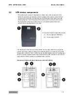
Page 19: ...the device also serves as an operation panel and is pre sented here as representative of all units Front panel of device Operating panel 1 Device indicator DISPLAY 2 Power switch On Off The backsides...

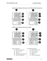
Page 20: ...VA 1000VA without Fan Illustration of the backside of the device 2000 VA Device model LSP A Device outlet port C13 B Power input C14 D USB port E Overvoltage protection LSP F Unit fan 1500 2000VA Ger...

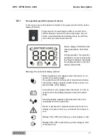
Page 21: ...he display remains on the infor mation selected last Meaning of the individual display symbols Mains operation mode appears when the device is con nected to the mains supply The symbol turns off in th...

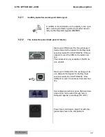
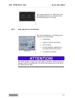
Page 22: ...and the signals for shutting down sensitive loads PC SHUT DOWN If the se rial port is used the USB port remains inac tive The serial port is only available in the RS de vice variants Device port USB p...

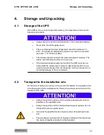
Page 23: ...exemplary fig UPS device identification The following infor mation is on the name plate model name data for connected load values articel number the CE and ROHS markings and the serial number for the...

Page 24: ...must be con nected with the mains power supply for approximately 24 hours to avoid a total discharge of the accumulators which would result in ir reversible damage to the accumulators 4 2 Transport to...

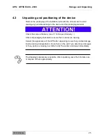
Page 25: ...cope of delivery see 14 Scope of delivery Check all packaging materials to ensure that no items are missing Inspect the appearance of the UPS after unpacking to see if any visible damage incurred duri...

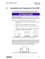
Page 26: ...er vertical installation position as specified The UPS may only be installed in a clean dry environment free of dust In addition air exchange according to EN62040 1 appendix M for devices with accumul...

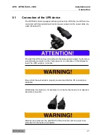
Page 27: ...UPS has been connected to the mains power supply it will start up automatically and switch to the charging mode An indication on the display fol lows The UPS output is not active Ensure that the wall...

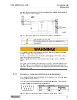
Page 28: ...ntion to the correct polarity between input and output for the UPS If the UPS is in the midst of an emergency stop circuit it must be observed that the UPS output is not completely currentless after t...

Page 29: ...port is a plug and play connection Additional actions are not necessary Please use the accompanying software to check the connection 5 1 3 Connection of the overvoltage module A data or telephone line...

Page 30: ...tting down of the system is done by the operating personnel The operator of the UPS system must always adhere to the instructions in this operating manual Only the operator can perform the following a...

Page 31: ...ad information can be accessed by touching the display The selected information is preserved provided the device operating mode has not been changed In the event that the background lighting of the di...

Page 32: ...PS Switching off occurs by means of activating the on off switch again The device switches the UPS outlet on whereby the charging unit remains The display changed to the image pictured here In the eve...

Page 33: ...oc curs 0 5 s interval In the event of a subsequent error a continu ous acoustic signal occurs 6 1 8 Error mode of the UPS When the UPS switches to the error mode e g due to overload the device switch...

Page 34: ...to the charging mode The UPS output remains off The corresponding image occurs in the display Now switch the UPS on and from here the UPS switches to the standard mode the UPS output is now active Ch...

Page 35: ...loads and restart the UPS Overcharging the inter nal battery bank Immediately contact the service hotline Degenerated or com pletely discharged bat tery bank Have qualified personnel change the accum...

Page 36: ...rmation status or warning or alarm messages Condition of the mains power supply load condition environment conditions temperature and moisture ventilation conditions Information of the condition such...

Page 37: ...asily via e mail mobile phone or fax The range of services can roughly be summarized as follows The availability for Windows 95 98 2000 NT XP Vista Win7 Novell Linux etc Local or network SHUTDOWN The...

Page 38: ...he support time autonomous time Before beginning with this procedure it is obligatory that all open data files must be secured Also inform all concerned employees of your intentions There are essentia...

Page 39: ...mponents accumulators Only EFFEKTA Regeltechnik service personnel or personnel of other accredited service points is allowed to replace accumulators or other UPS components During the replacement of a...

Page 40: ...remaining back up time or autonomous pe riod Professional cleaning of particular importance for the venti lation areas Proper disposal of defective or degenerate components Environmentally sound dispo...

Page 41: ...PS OFFICE 400 2000 Maintenance and Service OFFICE Series 41 Service Log Please always enter all maintenance and service work performed on the UPS into the service log Date Performed tasks Performed by...

Page 42: ...itchover Time typical 4 6 ms maximal 10 ms Battery Bank Voltage 12 VDC Capacity 1x 4 5 Ah 1x 7 Ah 1x 9 Ah Charging Time 12 h 80 of capacity reached Device Device Protection Overload Deep Discharge Ove...

Page 43: ...ttery Bank Voltage 24 VDC Capacity 2x 7 Ah 2x 9 Ah 2x 9 Ah Charging Time 6 h 90 of capacity reached Device Device Protection Overload Deep Discharge Overcharge Overvoltage Protection Protection of a d...

Page 44: ...Function View Description 1 x UPS OFFICE series according to your order 1 x Power cable Network connection cold device cable Schuko C13 1 x Power cable Load connection cold device cable C13 C14 1 x Op...

Page 45: ...pment Fig 15 1 SNMP adapter to connect the UPS to a network The SNMP adapter can easily be connected to the UPS as an external adapter via the serial port A standard patch cable enables access to the...

Page 46: ...eover the application of an external bypass allows for a cost efficient and clear installation of the UPS device 16 Wear parts The components listed below can show regular wear and are excluded from t...

Page 47: ...CE sign fulfill the EU harmonized standards and regula tions The EU declaration of conformity for this product is available upon request Please contact our 10 Service hotline You can also find the de...

Page 48: ...EFFEKTA Regeltechnik GmbH Rheinwaldstra e 34 D 78628 Rottweil...

Reviews: