background image

UPS MKD2000/3000 XL 


Manual 

MKD XL Series 


Page 33 of 45 


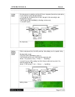
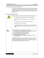
9.2.4  Starting the testing mode 


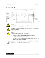
Before activating the testing service, you should consider following information: 

o


Inform involved users about your action. 

o


As a precaution save all data of the connected machines.  

o


Let all connected machines switched-on, so that the loading conduct 

can remain. 

o


Ensure that the UPS is in power supply mode. 

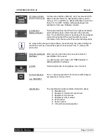
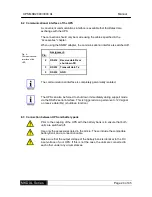
Push for about 3sec the buttons (2) “Menu-option” and (4) “Menu-up” to switch 

over into testing service. 


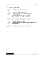
This operation mode is just a function test of the UPS. In this moment the 
display of the accumulator capacity is just a measurement of the loading 
condition of the battery pack. It is not the indication of the total battery backup 
capacity. 


9.2.5  Communication 

Corresponding software packages are necessary for data exchange between 

the UPS and the superior system. The product range you can see in chapter 

„Software“.  

Summary of Contents for ACX11MKS2K0000XL

Page 1: ...UPS Uninterruptible Power Supply MKD 2000 3000 XL Manual Item number ACX11MKS2K0000XL ACX11MKS3K0000XL Version V1 1 May 2010...

Page 2: ...7 6 3 Acoustic alert signs of the UPS 20 7 Storage and unpacking 21 7 1 Storage of the UPS 21 7 2 Unpacking the equipment 21 8 Installation and connecting of the UPS 22 8 1 Connecting the UPS 23 8 2 C...

Page 3: ...g and autonomy time 38 13 2 Replacing the batteries 38 13 3 Service log 39 13 4 Service hotline 40 13 5 Maintenance and service contracts 40 14 Technical data 41 14 1 Specifications 41 14 2 Scope of d...

Page 4: ...tion and tips Recycling symbol Denotes components that are governed by the electronic scrap ordinance Denotes components or parts that must be disposed of in a specific manner Never throw these compon...

Page 5: ...l disasters misuse vandalism inappropriate use maintenance errors or incorrect repairs by third parties Modifications unauthorized tampering incorrect operation another device or accessory incorrect i...

Page 6: ...losses or damage made by third parties against you Loss of or damage to your records or data or the cost of their recovery Financial consequential damage including loss of earnings or savings or incid...

Page 7: ...torage When storing equipment make sure that it is also securely positioned The equipment must not be transported or stored upside down Position the equipment securely during transportation taking its...

Page 8: ...r loads to the UPS which could overload the equipment e g laser printers The sum of the earth fault currents of all consumer loads connected to the UPS must not exceed 3 5mA Keep the connecting cables...

Page 9: ...ks and are capable of producing high short circuit currents which can also inflict burns Unauthorized persons must be kept away from batteries Do not place batteries against heat sources and do not th...

Page 10: ...e battery circuit before carrying out servicing or maintenance work and make sure that the equipment is isolated from the supply Work on batteries may only be performed and monitored by personnel with...

Page 11: ...ors in this description or their consequences The purpose of UPS equipment Uninterruptible Power Supply is to protect sensitive electrical devices such as computers workstations electronic points of s...

Page 12: ...the equipment and provides a general impression of how they interact If the mains power failure exceeds the autonomy time of the UPS it shuts down to prevent deep discharging of the batteries When th...

Page 13: ...fronted with the corresponding machine elements get instructions for the handling and get information concerning the connectings of the UPS 6 1 Handling elements on the front side Fig 2 display MKD se...

Page 14: ...ng displays can be indicated by pushing the up and down button o Actual status o INPUT VOLTAGE o OUTPUT VOLTAGE o INPUT FREQUENCY o OUTPUT FREQUENCY o BATTERY VOLTAGE o BATTERY CAPACITY o OUTPUT POWER...

Page 15: ...button 2 for about 3sec The UPS will be switched off by pushing this button at the same time as the menu up button 4 for about 3sec The menu display can be scrolled by pushing this button separately 4...

Page 16: ...display LED Function 5 NORMAL flashing mains existent UPS is switched off battery load duration mains existent UPS is switched on 6 WARNING UPS is in overload bypass or battery operation 7 FAULT Gene...

Page 17: ...UPS MKD2000 3000 XL Manual MKD XL Series Page 17 of 45 6 2 Elements on the back side Fig 3 back side view MKD2000 Fig 4 back side view MKD3000...

Page 18: ...vated and the UPS is immediately disconnected to the power supply b Power input MKD2000 Nema socket IEC 10A for mains voltage For connection use the enclosed three core socket b Power input MKD3000 Ne...

Page 19: ...t more information from the manual oft he external battery pack As a precaution always compare before connectioning the quoted voltage on the UPS as well as on the battery pack Those values have to co...

Page 20: ...Overload 100 125 The acoustic alert sounds in the following sequence B beep short pause 1 sec beep repeating Normal operation and overload 125 150 The acoustic alert sounds in the following sequence...

Page 21: ...k optional must be operated for a period of approx 8 hours to prevent deep discharging of the batteries 7 2 Unpacking the equipment Remove the shipping cartons and packaging material Always store the...

Page 22: ...rails during installation The load bearing capacity of the support must be sufficient Observe the specified installation location and only mount the equipment using the screw in positions Make sure th...

Page 23: ...ive earth conductor must always be connected If not the consumer loads will also not be earthed In generator mode the connection of the UPS hast o be polarized Warning The connection diagram shown in...

Page 24: ...communicational interface is completely galvanically isolated The UPS can also be forced to shut down immediately during support mode via the RS232 serial interface This is triggered via a permanent 1...

Page 25: ...4 Connection sequence Connect the UPS to the mains making sure that the mains and UPS are safely switched off beforehand Before connecting the consumer with the output the basic configuration 9 2 3 ha...

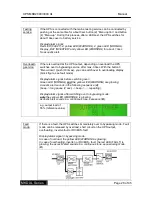
Page 26: ...s in bypass mode and there is output voltage Display alarm signals The green LED NORMAL is flashing and the acoustic alert sounds in the following sequence E beep long pause 2 min beep repeating Witho...

Page 27: ...l Just the green LED NORMAL is flashing continuously no acoustic signal On line mode Battery backup mode If the mains power fails the UPS switches immediately over to support mode Display alarm signal...

Page 28: ...ch over to overloading display block figure see fault mode Display alarm signal before switching over Green LED NORMAL and the yellow LED WARNING are glowing Acoustic alert sounds in the following seq...

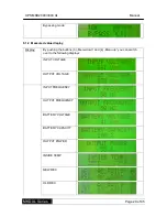
Page 29: ...9 1 2 Measured value display Display By pushing the buttons 3 Menu down and 4 Menu up you can switch over to the following displays INPUT VOLTAGE OUTPUT VOLTAGE INPUT FREQUENCY OUTPUT FREQUENCY BATTE...

Page 30: ...Due to extensive protection functions which the UPS ensures to its connected machines the UPS is working completely automatically Just the switching on and the starting or the switching off has to be...

Page 31: ...must be disconnected to the charge output o Ensure that the UPS is switched off o The new settings will first be adopted after a complete new start of the UPS switching off disconnect the line cord an...

Page 32: ...cy can be changed by using the buttons 3 Menu down and 4 Menu up OUTPUT e g 230VAC 50Hz inactive bypass Output frequency can have the following settings 50Hz output frequency 50Hz inactive bypass 60Hz...

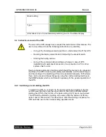
Page 33: ...sure that the UPS is in power supply mode Push for about 3sec the buttons 2 Menu option and 4 Menu up to switch over into testing service This operation mode is just a function test of the UPS In this...

Page 34: ...is in power supply mode 5 Now start to connect the consumer loads successively and observe the load display If all steps have been made the UPS has to be now in the power supply mode and the load disp...

Page 35: ...hows Overload fault acoustic alert sounds The UPS is overloaded with regard to the connected machines Disconnect the connected machines or a part of it from the UPS until the load display indicates 10...

Page 36: ...ins the accumulators have to be exchanged The UPS is ok but the connected machine does not work The connection between UPS and the machine is defective Check the connection and confirm it by voltage m...

Page 37: ...site http www effekta com The following basic functions are supported by all software packages o Capture and display of the mains condition of the UPS o Display of the UPS output condition o Capture a...

Page 38: ...wo methods of measuring the autonomy time Method a is suitable for measuring the actual autonomy time whereby the consumer loads will inevitably have zero current at the end of the bridging time Metho...

Page 39: ...ludes the voltage in the battery pack and the charging voltages in mains capacitors for example Appropriate safety measures must be taken to prevent electric shock Owing to the dangers described above...

Page 40: ...com html kontakt html 13 5 Maintenance and service contracts EFFEKTA Regeltechnik GmbH offers you tailored maintenance and customer services that ensure the highest possible reliability and availabil...

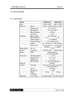
Page 41: ...nce 0 5 battery service Overload 105 150 f r 30 s 150 f r 200ms Autonomy time ca 7 min normal conditions ca 6 min normal conditions Efficiency factor DC AC 90 DC input Input voltage 96 V DC nominal 96...

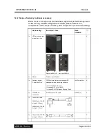
Page 42: ...iew Item number 1x UPS electronics incl internal batteries Rear view 2000 VA rear view 3000 VA X 1x Manual Printed manual English X 1x Software bundle PowerShut Plus CD ROM with Network compatible UPS...

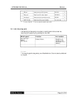
Page 43: ...rk interface GE 32CS121MINI O X scope of delivery O can be ordered separately as an option 14 3 List of wearing parts The following components are subject to normal wear and tear and are therefore not...

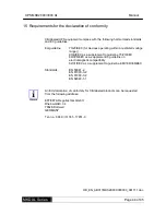
Page 44: ...e range 93 EEC as a supplement to guideline 73 23 EEC 89 336 EEC as a supplement to guideline on electromagnetic compatibility 92 31 EEC as a supplement to guideline EMV 89 336 EEC Standards EN 50091...

Page 45: ...UPS MKD2000 3000 XL Manual MKD XL Series Page 45 of 45...

Reviews: