background image

Digital Video Recorder User Manual 

110 


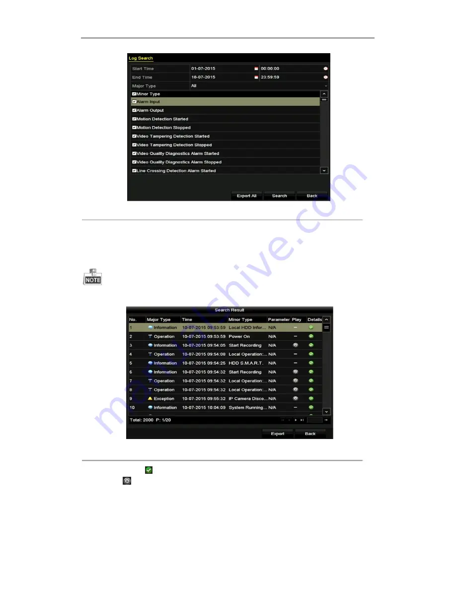
Figure 10. 2 Log Search Interface 


2.   

Set the log search conditions to refine your search, including the Start Time, End Time, Major Type and 


Minor Type. 


3.   

Click the 

Search 

button to start search log files. 


4.   

The matched log files will be displayed on the list shown below. 


Up to 2000 log files can be displayed each time. 


Figure 10. 3 Log Search Results 


5.   

You can click the  

  button of each log or double-click it to view its detailed information. And you can also 

click the 

  button to view the related video files if available. 

6.   

If you want to export the log files, click the 

Export 

button to enter the Export menu, as shown in Figure 10. 


4. 

Summary of Contents for SP-8HDSET

Page 1: ...Digital Video Recorder User Manual SP 8HDSET EFB Elektronik GmbH www efb elektronik de...

Page 2: ...rmation FCC Information FCC compliance This equipment has been tested and found to comply with the limits for a Class A digital device pursuant to part 15 of the FCC Rules These limits are designed to...

Page 3: ...eglected Cautions Injury or equipment damage may occur if any of the cautions are neglected Warnings Follow these safeguards to prevent serious injury or death Cautions Follow these precautions to pre...

Page 4: ...is device Improper use or replacement of the battery may result in hazard of explosion Replace with the same or equivalent type only Dispose of used batteries according to the instructions provided by...

Page 5: ...matic cycle can be adjusted Quick setting menu is provided for live view The selected live view channel can be shielded Motion detection video tampering detection video exception alarm video loss alar...

Page 6: ...l Functions Manual and automatic video quality diagnostics Operable by mouse and remote control Three level user management admin user can create many operating account and define their operating perm...

Page 7: ...start stop recording Remotely start stop alarm output Remote PTZ control Remote JPEG capture Two way audio and voice broadcasting Embedded WEB server Development Scalability SDK for Windows and Linux...

Page 8: ...4 HDMI and VGA Non Simultaneous Output 24 3 7 5 Quick Setting Toolbar in Live View Mode 25 3 8 Adjusting Live View Settings 26 3 9 Manual Video Quality Diagnostics 28 3 10 User Logout 29 Chapter 4 PTZ...

Page 9: ...rd Files 64 7 1 1 Backing up by Normal Video Search 64 7 1 2 Backing up by Event Search 66 7 1 3 Backing up Video Clips 67 7 2 Managing Backup Devices 68 Chapter 8 Alarm Settings 69 8 1 Setting Motion...

Page 10: ...05 9 11 Configuring Privacy Mask 106 9 12 Configuring Video Parameters 107 Chapter 10 DVR Management and Maintenance 109 10 1 Viewing System Information 109 10 2 Searching Log Files 109 10 3 Importing...

Page 11: ...ion 2 1 Front Panel Figure 2 1 Front Panel Table 2 1 Description of Front Panel No Icon Description 1 Turns red when DVR is powered up 2 Turns red when data is being read from or written to HDD 3 Flic...

Page 12: ...from your provider The operation of the mouse Table 2 2 Description of the Mouse Control Name Action Description Left Click Single Click Live view Select channel and show the quick set menu Menu Sele...

Page 13: ...2 2 Soft Keyboard Description of the buttons on the soft keyboard Table 2 3 Description of the Soft Keyboard Icons Icon Description Icon Description Number English letter Lowercase Uppercase Backspac...

Page 14: ...n of Front Panel No Item Description 1 VIDEO IN BNC interface for TVI and analog video input Up to 8 ch 2 HDMI HDMI video output connector 3 VGA DB15 connector for VGA output Display local video outpu...

Page 15: ...Power Supply UPS be used in conjunction with the device 2 Turn on the power switch on the rear panel and the Power indicator LED should turn on indicating that the unit begins to start up 3 After star...

Page 16: ...gure 3 3 Settings Admin Password STRONG PASSWORD RECOMMENDED We highly recommend you create a strong password of your own choosing using a minimum of 8 characters including upper case letters lower ca...

Page 17: ...through some important settings of the device If you don t want to use the Start Wizard at that moment click Exit You can also choose to use the Start Wizard next time by leaving the Start wizard when...

Page 18: ...gured the basic network parameters Then you will enter the Cloud P2P interface Configure the Cloud P2P according to your need Figure 3 8 Advanced Network Configuration 5 Click Next button to enter the...

Page 19: ...n will remove all the data saved in the HDD 9 Click Next to enter the IP Camera Management window only supported by HDVR series 10 Click Search to search the online IP Camera and the Security status s...

Page 20: ...fter finishing IP Camera settings click Next to enter the Record Settings window 12 Click the icon and you can enable the continuous recording or motion Detection recording for all channels of the dev...

Page 21: ...Login Interface 2 Input Password 3 Click OK to log in In the Login dialog box if you have entered the wrong password for 7 times the current user account will be locked for 60 seconds Figure 3 14 Use...

Page 22: ...times depending on which menu you re on will bring you to the Live View mode Live View Icons In the live view mode there are icons at the right top of the screen for each channel showing the status o...

Page 23: ...output 1 VGA HDMI 3 7 3 Using the Mouse in Live View Table 3 3 Mouse Operation in Live View Name Description Menu Enter the main menu of the system by right clicking the mouse Single Screen Switch to...

Page 24: ...dd IP Camera is not supported 3 7 4 HDMI and VGA Non Simultaneous Output DVR support HDMI and VGA non simultaneous output Steps 1 Enter the Configuration Menu Menu Configuration 2 Click More Settings...

Page 25: ...ontrol Digital Zoom Image Settings Close Live View Instant Playback only shows the record in last five minutes If no record is found it means there is no record during the last five minutes Digital Zo...

Page 26: ...Live View settings can be customized according to different needs You can configure the output interface dwell time for screen to be shown mute or turning on the audio the screen number for each chann...

Page 27: ...ell Time The time in seconds to show alarm event screen 2 Set the camera order 1 Select View tab Figure 3 22 Live View Camera Order 2 Click a window to select it and then double click a camera name in...

Page 28: ...ual Manual Video Quality Diagnostics Figure 3 23 Video Quality Diagnostics 2 Check the checkboxes to select the channels for diagnostics 3 Click the button Diagnose and the results will be displayed o...

Page 29: ...user name and password to log in again Steps 3 Enter the Shutdown menu Menu Shutdown Figure 3 25 Shutdown 4 Click Logout Chapter 4 PTZ Controls 4 1 Configuring PTZ Settings Purpose Follow the procedur...

Page 30: ...arameters of the PTZ camera All the parameters should be exactly the same as the PTZ camera parameters For the Coaxitron camera dome connected you can select the PTZ protocol to VISION C Coaxitron Mak...

Page 31: ...re 4 3 PTZ Settings 2 Use the directional button to wheel the camera to the location where you want to set preset and the zoom and focus operations can be recorded in the preset as well 3 Enter the pr...

Page 32: ...corresponding text field 5 Click the Call Preset button to call it When the Coaxitron camera dome connected and the PTZ protocol is selected to VISION C Coaxitron you can call the preset 95 to enter t...

Page 33: ...the patrol The Duration refers to the time span to stay at the corresponding key point The Speed defines the speed at which the PTZ will move from one key point to the next 5 Click the Add button to a...

Page 34: ...in the dropdown list and click the Call Patrol button to call it 4 You can click the Stop Patrol button to stop calling it 4 2 5 Customizing Patterns Purpose Patterns can be set by recording the move...

Page 35: ...the PTZ Control icon in the quick setting bar or select the PTZ option in the right click menu to show the PTZ control panel 2 Click the button to show the general settings of the PTZ control Figure...

Page 36: ...on the left side of the right limit as well the angle from the left limit to the right limit should be no more than 180 4 2 8 Calling Linear Scan Purpose Follow the procedure to call the linear scan...

Page 37: ...he front panel or click the PTZ Control icon in the quick setting bar to enter the PTZ setting menu in live view mode 2 Click the button to show the one touch function of the PTZ control Figure 4 12 P...

Page 38: ...In PTZ control mode the PTZ panel will be displayed when a mouse is connected with the device If no mouse is connected the icon appears in the lower left corner of the window indicating that this came...

Page 39: ...check the storage mode of the HDD 1 Whether the HDD mode is Quota please set the maximum record capacity For detailed information see Chapter 9 4 Configuring Quota Mode 2 If the HDD mode is Group you...

Page 40: ...eam Continuous and Main Stream Event respectively The resolution of 1920 1080 1080p Lite is supported 3 Click More Settings to configure more parameters Figure 5 4 More Settings of Record Parameters P...

Page 41: ...able 960 Mode The option is supported by analog cameras Enabling the 960 mode to enable the WD1 resolution for the main stream otherwise the resolution supports up to 4CIF And the option does not supp...

Page 42: ...DVR support continuous motion and event triggered recording types and other models support continuous alarm motion motion alarm motion alarm and event triggered recording types In this chapter we take...

Page 43: ...motion detection or alarm M A recording triggered by motion detection and alarm 2 Choose the camera you want to configure in the Camera dropdown list 3 Check the checkbox of Enable Schedule 4 Configur...

Page 44: ...ation refer to Chapter 8 1 Chapter 8 8 and Chapter 9 The VCA settings are only available to the smart IP cameras Repeat the above steps 1 4 to schedule recording for other days in the week If the sche...

Page 45: ...lick Apply in the Record Schedule interface to save the settings 5 3 Configuring Motion Detection Recording Purpose Follow the steps to set the motion detection parameters In the live view mode once a...

Page 46: ...nnel information pops up Figure 5 14 Motion Detection Settings 5 Select the channels which you want the motion detection event to trigger recording 6 Click Apply to save the settings 7 Click OK to bac...

Page 47: ...k the status icon of Analog to disable manual record of all channels After rebooting all the manual records enabled are canceled 5 5 Configuring Holiday Recording Purpose Follow the steps to configure...

Page 48: ...e Please refer to the Chapter 5 2 Configuring Record Schedule while you may choose Holiday in the Schedule dropdown list or you can draw the schedule on the timeline of Holiday Figure 5 18 Edit Schedu...

Page 49: ...ce Menu Export Figure 5 19 Export 2 Select the channels you want to investigate by checking the checkbox to 3 Configure the record type file type start time and end time 4 Click Search to show the res...

Page 50: ...l 2 Click to edit the HDD you want to protect Figure 5 22 HDD General Editing 3 Set the HDD to Read only 4 Click OK to save settings and back to the upper level menu You cannot save any files in a Rea...

Page 51: ...eal time is supported Steps 1 Enter the Record menu Menu Record 2 Click Advanced to enter the advanced interface Figure 5 23 Advanced Interface 3 Check the checkbox of 1080p Lite Mode and click Apply...

Page 52: ...annel Steps Choose a channel in live view mode and click the button in the quick setting toolbar In the instant playback mode only record files recorded during the last five minutes on this channel wi...

Page 53: ...duration Multi channel simultaneous playback and channel switch are supported Steps 1 Enter playback interface Menu Playback 2 Check the checkbox of channel s in the channel list and then double clic...

Page 54: ...itch playback to another channel or execute simultaneous playback of multiple channels Toolbar of Playback Table 6 1 Detailed Explanation of Playback Toolbar Button Operation Button Operation Button O...

Page 55: ...Event Playback interface 3 Select Alarm Input Motion Line Crossing Detection Intrusion Detection as the event type and specify the start time and end time for search Figure 6 5 Video Search by Motion...

Page 56: ...of event triggered record files Pre play The time you set to play back before the event For example when an alarm triggered the recording at 10 00 if you set the pre play time as 5 seconds the video p...

Page 57: ...nter Playback interface Menu Playback 2 Search and play back the record file s Refer to Chapter 6 1 2 Playing Back by Channel for the detailed information about searching and playback of the record fi...

Page 58: ...select the previous or next tag Please refer to Table 6 1 for the description of buttons on the toolbar 6 1 5 Playing Back by Smart Search Purpose The smart playback function provides an easy way to g...

Page 59: ...ult Filter function is supported by the IP camera only 6 1 6 Playing Back by System Logs Purpose Play back record file s associated with channels after searching system logs Steps 1 Enter Log Informat...

Page 60: ...4 Playback management The toolbar in the bottom part of Playback interface can be used to control playing process Figure 6 14 Interface of Playback by Log 6 1 7 Playing Back by Sub Periods Purpose Th...

Page 61: ...es existing between 16 00 and 22 00 and the 6 screen display mode is selected then it can play the video files for 1 hour on each screen simultaneously 6 1 8 Playing Back External File Purpose Perform...

Page 62: ...mal events happen Steps Using a Mouse Go to Playback interface and click button until the speed changes to Single frame One click on the playback screen represents playback or adverse playback of one...

Page 63: ...nel Purpose You can play back record files of multi channel reversely Up to 16 ch simultaneous reverse playback is supported Steps 1 Enter Playback interface Menu Playback 2 Check more than one checkb...

Page 64: ...USB flash drives and USB HDDs Steps 1 Enter Export interface Menu Export Normal 2 Select the cameras to search 3 Set search condition and click Search button to enter the search result interface Figu...

Page 65: ...ort interface Figure 7 3 Export by Normal Video Search using USB Flash Drive 6 Select the backup device from the drop down list and you can also select the file format to filter the files existing in...

Page 66: ...rpose Back up event related record files using USB devices USB flash drives USB HDDs USB writer Quick Backup and Normal Backup are supported Steps 1 Enter Export interface Menu Export Event 2 Select t...

Page 67: ...in playback mode to export directly during Playback using USB devices USB flash drives USB HDDs USB writer Steps 1 Enter Playback interface 2 During playback use buttons or in the playback toolbar to...

Page 68: ...Folder button if you want to create a new folder in the backup device Select a record file or folder in the backup device and click button if you want to delete it Click Erase button if you want to e...

Page 69: ...8 1 Motion Detection Setup Interface 2 Set detection area and sensitivity Check checkbox to enable motion detection use the mouse to draw detection area s and drag the sensitivity bar to set sensitivi...

Page 70: ...periods shall not be repeated or overlapped Figure 8 4 Set Arming Schedule of Motion Detection 5 Click Linkage Action tab to set up alarm response actions of motion alarm please refer to Chapter 8 6...

Page 71: ...Loss Setup Interface 2 Set up handling method of video loss Check the checkbox of Enable Video Loss Alarm Click button to set up handling method of video loss 3 Set arming schedule of the channel Sele...

Page 72: ...Setting Alarm Response Actions 5 Click the OK button to complete the video loss settings of the channel Repeat the above steps to finish settings of other channels or click the Copy button copy the a...

Page 73: ...iods shall not be repeated or overlapped Figure 8 8 Set Arming Schedule of Video Tampering 3 Select Linkage Action tab to set alarm response actions of video tampering alarm please refer to Chapter 8...

Page 74: ...set the harder the exception will be detected 4 Click to set handling method of video quality diagnostics Set arming schedule and alarm response actions of the channel 1 Click Arming Schedule tab to s...

Page 75: ...o space for saving recorded files Steps 1 Enter Exceptions interface and handle various exceptions Menu Configuration Exceptions Figure 8 10 Exception Settings Interface 2 Check the checkbox of Enable...

Page 76: ...well time can be set by going to Menu Configuration Live View Auto switch will terminate once the alarm stops and you will be taken back to the Live View interface Audible Warning Trigger an audible b...

Page 77: ...tion Network Figure 8 13 Network Settings Interface 2 Select the General tab 3 In the General Settings interface you can configure the following settings IPv4 Address IPv4 Gateway MTU and DNS Server I...

Page 78: ...automatically connected after reboot You can go to Menu Maintenance System Info Network interface to view the status of PPPoE connection 8 8 2 Configuring Cloud P2P Purpose Cloud P2P provides the mob...

Page 79: ...he help file on the official website http www hicloudcam com 8 8 3 Configuring DDNS Purpose If your DVR is set to use PPPoE as its default network connection you may set Dynamic DNS DDNS to be used fo...

Page 80: ...in the DynDNS website Figure 8 17 DynDNS Settings Interface PeanutHull Enter the User Name and Password obtained from the PeanutHull website Figure 8 18 PeanutHull Settings Interface NO IP Enter the a...

Page 81: ...the HiDDNS server or define a new device domain name If a new alias of the device domain name is defined in the NVR it will replace the old one registered on the server You can register the alias of...

Page 82: ...r Manual 82 Figure 8 21 Register an Account 2 Click to register an account if you do not have one and use the account to log in Figure 8 22 Register an Account 3 In the Device Management interface cli...

Page 83: ...Domain Name on the device or the Device Name on the HiDDNS server Example http www hiddns com nvr1 If you mapped the HTTP port on your router and changed it to port No except 80 you have to enter htt...

Page 84: ...Settings Interface 3 Check the Enable NTP checkbox to enable this feature 4 Configure the following NTP settings Interval Time interval between the two synchronizing actions with NTP server The unit...

Page 85: ...oute of the device should be in the same network segment as that of the LAN IP address of the router Steps 1 Enter the Network Settings interface Menu Configuration Network 2 Select the NAT tab to ent...

Page 86: ...iple devices are configured for the UPnP settings under the same router the value of the port No for each device should be unique Figure 8 28 External Port Settings Dialog Box 2 Click Apply button to...

Page 87: ...vers Enter the RTSP port in the text field of RTSP Port The default RTSP port is 554 and you can change it according to different requirements Server Port and HTTP Port Enter the Server Port and HTTP...

Page 88: ...igned Certificate 2 Enter the country host name IP validity and other information 3 Click OK to save the settings OPTION 2 Create the authorized certificate 1 Click the Create button to create the cer...

Page 89: ...on Network 2 Select the Email tab to enter the Email Settings interface Figure 8 35 Email Settings Interface 3 Configure the following Email settings Enable Server Authentication optional Check the ch...

Page 90: ...your Email settings work The corresponding Attention message box pops up Figure 8 36 Email Testing Attention 8 9 Checking Network Traffic Purpose You can check the network traffic to obtain real time...

Page 91: ...text field of Destination Address 5 Click the Test button to start testing network delay and packet loss 8 10 2Exporting Network Packet Purpose By connecting the DVR to network the captured network da...

Page 92: ...us Purpose You can also check the network status and quick set the network parameters in this interface Steps Click Status on the right bottom of the page Figure 8 40 Checking Network Status If the ne...

Page 93: ...real time information of the device Steps 1 Enter the Network Statistics interface Menu Maintenance Net Detect 2 Click the Network Stat tab to enter the Network Statistics menu Figure 8 43 Network Sta...

Page 94: ...h your DVR Steps 1 Enter the HDD Information interface Menu HDD General Figure 9 1 HDD Information Interface 2 Select HDD to be initialized 3 Click the Init button Figure 9 2 Confirm Initialization 4...

Page 95: ...e HDD Sleeping Check the checkbox of Enable HDD Sleeping by default and the HDDs which are free of working for a long time will be set to sleep Uncheck the checkbox of Enable HDD Sleeping and the HDDs...

Page 96: ...vailable NAS disks 3 Select the NAS disk from the list shown below Or you can just manually enter the directory in the text field of NetHDD Directory 4 Click OK to add the configured NAS disk Up to 8...

Page 97: ...st If the added NetHDD is uninitialized please select it and click the Init button for initialization Figure 9 10 Initialize Added NetHDD 9 3 Managing HDD Group 9 3 1 Setting HDD Groups Purpose Multip...

Page 98: ...activate the changes 5 After reboot of device enter the HDD Information interface Menu HDD General 6 Select HDD from the list and click the icon to enter the Local HDD Settings interface as shown in F...

Page 99: ...erty is set to redundancy the video can be recorded both onto the redundancy HDD and the R W HDD simultaneously so as to ensure high security and reliability of video data Steps 1 Enter the HDD Inform...

Page 100: ...rface 3 Select a camera for which you want to configure quota 4 Enter the storage capacity in the text field of Max Record Capacity GB 5 You can copy the quota settings of the current camera to other...

Page 101: ...tion interface Menu HDD General 2 Check the status of each HDD which is displayed on the list as shown in Figure 9 18 Figure 9 18 View HDD Status 1 If the status of HDD is Normal or Sleeping it works...

Page 102: ...pes of anticipating failures Steps 1 Enter the HDD Detect interface Menu Maintenance HDD Detect 2 Click the S M A R T Settings tab to enter the interface 3 Select the HDD to view its S M A R T informa...

Page 103: ...Figure 9 21 Bad Sector Detection 2 Click the Bad Sector Detection tab to enter the interface 3 Select a HDD and click the Detect button to start detecting Figure 9 22 Bad Sector Detecting 4 You can c...

Page 104: ...tion s for HDD error as shown in Figure 9 23 The linkage actions can be selected to Audible Warning Notify Surveillance Center Send Email Please refer to Chapter 8 6 Setting Alarm Response Actions Fig...

Page 105: ...era name etc Steps 1 Enter the OSD Configuration interface Menu Camera OSD 2 Select the camera to configure OSD settings 3 Edit the Camera Name in the text field 4 Configure the Display Name Display D...

Page 106: ...nes that cannot be viewed or recorded by the operator Steps 1 Enter the Privacy Mask Settings interface Menu Camera Privacy Mask 2 Select the camera to set privacy mask 3 Check the checkbox of Enable...

Page 107: ...privacy mask settings of the current camera to other cameras Please refer to step 7 of Chapter 9 10Configuring OSD Settings 7 Click the Apply button to save the settings 9 12 Configuring Video Parame...

Page 108: ...each other 4 Select the mode from the drop down list of Mode there are four modes selectable Standard Indoor Dim Light and Outdoor 5 Adjust the image parameters according to actual needs The paramete...

Page 109: ...nfo Camera Record Alarm Network and HDD tabs to view the system information of the device Figure 10 1 System Information Interface This alarm information is not available for the DVR 10 2 Searching Lo...

Page 110: ...files 4 The matched log files will be displayed on the list shown below Up to 2000 log files can be displayed each time Figure 10 3 Log Search Results 5 You can click the button of each log or double...

Page 111: ...not supported DVR Purpose The information of added IP camera can be generated into an excel file and exported to the local device for backup including the IP address manage port password of admin etc...

Page 112: ...2 Click the Export button to export configuration files to the selected local backup device 3 To import a configuration file select the file from the selected backup device and click the Import button...

Page 113: ...gure PC running FTP server and DVR to the same Local Area Network Run the 3rd party TFTP software on the PC and copy the firmware into the root directory of TFTP Steps 1 Enter the Upgrade interface Me...

Page 114: ...ddress subnet mask gateway MTU NIC working mode default route server port etc and user account parameters to the factory default settings Factory Defaults Restore all parameters to the factory default...

Page 115: ...face Resolution Select the output resolution which must be the same with the resolution of the VGA HDMI display Time Zone Select the time zone Date Format Select the date format System Date Select the...

Page 116: ...eneral Settings interface Menu Configuration General 2 Click the More Settings tab to enter the More Settings interface as shown in Figure 15 3 Figure 11 3 More Settings Interface 3 Configure the foll...

Page 117: ...e for the first time The Administrator has the permission to add and delete user and configure user parameters 11 4 1Adding a User Steps 1 Enter the User Management interface Menu Configuration User F...

Page 118: ...way Audio in Remote Configuration and all operating permission in Camera Configuration by default Guest The Guest user has no permission of Two way Audio in Remote Configuration and only has the local...

Page 119: ...en the remote client and the device Remote Alarm Control Remotely arming notify alarm and exception message to the remote client Remote Advanced Operation Remotely operating HDD management initializin...

Page 120: ...9 Figure 11 9 Edit User Interface 4 Edit the corresponding parameters Operator and Guest You can edit the user information including user name password permission level and MAC address Check the chec...

Page 121: ...and HD TVI video input 8 ch BNC interface 1 0Vp p 75 Supported camera types 720p 25 720p 30 720p 50 720p 60 1080p 25 1080p 30 CVBS Audio compression G 711u Audio input Two way audio in 1 ch RCA 2 0 Vp...

Page 122: ...DHCP clients to obtain configuration information for operation in an Internet Protocol network HTTP Acronym for Hypertext Transfer Protocol A protocol to transfer hypertext request and information bet...

Page 123: ...the connection cable is good If there is still no image display on the monitor after rebooting please check if the connection cable is good and change a cable to connect again 3 Verify Input mode of...

Page 124: ...m our company to do the further process When using the device to get the live view audio there is no sound or there is too much noise or the volume is too low Possible Reasons a Cable between the pick...

Page 125: ...ou search the record files Possible Reasons a The time setting of system is incorrect b The search condition is incorrect c The HDD is error or not detected Steps 1 Verify the system time setting is c...

Reviews: