REF. 08705
EN
INSTRUCTION MANUAL
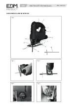
Collecting with the dust extraction facility (Fig. 7)
This machine is supplied with a dust extraction facility.
The dust extraction adaptor will allow the jig saw to be
connected to most vacuum cleaners. This will prevent you
from inhaling the dust.
Do not use the jig saw if a dust collection system is not
installed.
This jig saw is supplied with a dust collection button and
always ensure the jig saw to be connected with vacuum
cleaners:
Push the button to left position when start working, then the
dust will be collected inside machine to prevent you from
inhaling the dust.
Push the button to right position when finish working, then
the dust will be blow outside the machine.
Term of use
When all precautions have been taken and the previous
operations were done, you can start working.
Always secure the workpiece.
Use the right blade for the material and finish you want. The
stress on the machine should not be such that the speed is
reduced by more than 25% for significant periods. When
overloaded happened, run the machine empty for 3 to 5
minutes to cool the engine. For circular or curved cuts, use a
narrow blade and gradually turn the machine along the path.
For pocket cuts, rest on the front of the sole with a 60/70 °
angle and dive gradually the blade in the wood (this
operation is only possible in soft woods). Do not put down the
saw until the blade is stopped. Beware of harmful and toxic
dusts can be produced when using the saw on certain
materials. These dusts can seriously affect the health of the
user or people around. Always wear a protective mask when
working and keep spectators away from the work area!
Care and Maintenance
Keep the ventilation openings clear and clean the product
regularly. This machine requires no special mechanical
maintenance such as greasing the bearings.
If something unusual occurs during use, switch off the supply
and disconnect the plug. Inspect and repair the tool before
using it again. The repairs must be carried out by a qualified
technician.
Repair of the tool must only be carried out by a qualified
repair technician.
Repair or maintenance by unqualified personnel can lead to
a risk of injury.
Use only identical spare parts for repairing a tool.
Caution! If the supply cord of this power tool is damaged, it
must be replaced by a specially prepared
Push the button to left position when start working, then the
dust will be collected inside machine to prevent you from
inhaling the dust.
Push the button to right position when finish working, then
the dust will be blow outside the machine.
cord available through the service organization.
Care and cleaning
Cleaning of plastic parts is disconnected machines, using a
soft damp cloth and a mild soap.
Never immerse the machine and do not use detergent,
alcohol, petrol, etc..
In case of problems or for a deep cleaning, consult the
manufacturer, its service agent or a similarly qualified person
to avoid a hazard.
Operating Instructions
The jig saw is delivered as assembled, except for the blade.
The jig saw is mainly intended for woodworking.
Choose the blade adapted to the work to be done.
Saw blade installation (Fig.2)
WARNING. Switch off the jigsaw and unplug from power
point before fitting blades.
Note: When changing blades, set pendulum action switch to
“0”.
1. This jig saw is equipped with a tool free blade holder.
2. To open the blade holder, press the lever (jigsaw upside
down) and hold in position.
3. Then fully insert the blade into the blade holder slot with
blade teeth facing forward and release the lever.
4. Push the blade into the blade holder again to ensure it is
locked in position. Ensure the edge of the blade is located in
the groove of the support roller.
5. To remove blade, hold the blade and push the lever then lift
out the blade.
Using the parallel guide (Fig.3)
Parallel guide can be used for making cuts parallel to a work
piece edge at a chosen distance.
1. Slide the parallel guide arm through the slot.
2. Tighten the screw to lock it into position.
This guide can be used from both sides of the base plate.
Pendulum action switch adjustment (Fig. 4)
The adjustable 4-stage pendulum action makes it possible to
adjust the blade penetration on the upward stroke for the
various working materials.
Optimal cutting performance is thereby achieved.
The saw blade is lifted from the workpiece on the downward
stroke. This results in improved chip ejection while
substantially reducing frictional heat and increasing the life
expectancy of the saw blade.
The pendulum action can be adjusted to one of four stages
with pendulum action knob.
The setting can be changed while the machine is operating:
Stage 0: Pendulum action off
Stage 1: Low pendulum action
Stage 2: Moderate pendulum action
Stage 3: High pendulum action
The following should be observed:
1. The pendulum action should be off when working with thin
materials such as sheet metal.
2. If smoothly cut edges are desired in soft material, select low
stage or shut off pendulum action.
3. Use low pendulum action when working with hard
materials such as steel.
4. Use high pendulum action when working with most soft
materials such as wood and plastic.
5. The optimum setting can be determined in practical trials
on scrap material.
Shoe plate adjustment (Fig. 5)
1. Loosen the two locking screws under the shoe plate with
the supplied hex key.
2. Adjust the base plate to obtain the desired cutting angle
(see the graduations on the
sole 15 ° to 45 °), and then lock the screws tightly.
On/Off Switch (Fig. 6)
1. Start the tool by squeezing the trigger switch.
2. To stop the tool by releasing the trigger switch
3. Pressing the switch lock button while the trigger switch is
engaged will allow the jigsaw to continue operating without
constant pressure on the trigger switch.
4. To turn off while in this mode, re-press the trigger switch.
5. The speed could be adjusted by rotating the speed
adjustment knob on the trigger switch.

