background image

16

Names of Things and What They Do

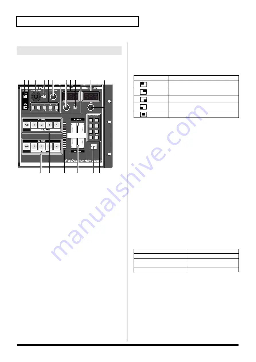
This section is used for controlling the switching, P in P, key composite, 
and other functions for the HD/RGB video.

1.

P in P Button (HD/RGB)  ................................................. (p. 34)

When this button is lit, the position of the subscreen when the P in P effect is 
used in the HD/RGB section can be set with the POSITION joystick (HD/
RGB), while the subscreen size can be set with the SIZE/ZOOM knob (HD/
RGB).

2.

PAN/ZOOM Button (HD/RGB) .......................................  (p. 34)

When using the P in P effect in the HD/RGB section, the crop position 
and zoom ratio of the small screen can be set with the POSITION/PAN 
joystick (HD/RGB) and SIZE/ZOOM knob (HD/RGB) knob when this 
button is lit.

3.

POSITION/PAN Joystick (HD/RGB)  .............................. (p. 34)

This adjusts the position of, and zoom for the small screen when the P in 
P effect is used in the HD/RGB section. 
The POSITION/PAN joystick (HD/RGB) can be used only when the 
LOCK button to the right of the POSITION/PAN joystick (HD/RGB) is 
pressed to release the lock.

4.

LOCK Button (HD/RGB) ................................................. (p. 34)

When the LOCK button (HD/RGB) is lit, neither the position nor panning of 
the P in P subscreen be changed with the POSITION/PAN joystick (HD/RGB).

Pressing the LOCK button (HD/RGB) so enables operation with the 
POSITION/PAN joystick (HD/RGB).

5.

P in P PATTERN Buttons (HD/RGB) 1–5 .......................(p. 33)

Pressing the P in P PATTERN 1–5 buttons (HD/RGB) applies the P in P 
effect in the HD/RGB section.
When the P in P effect is applied, the selected P in P PATTERN button 
(HD/RGB) lights up.

6.

SIZE/ZOOM Knob (HD/RGB)  ..........................................(p. 34)

This adjusts the size of the small screen when the P in P effect is used in 
the HD/RGB section. 

7.

KEY LEVEL Knob (HD/RGB)  ..........................................(p. 36)

This adjusts the key level when key composite effects are used in the 
HD/RGB section. 

8.

KEY LEVEL Display (HD/RGB) ...................................... (p. 36)

This indicates the value of the key level set with the (7.) KEY LEVEL knob 
(HD/RGB).

9.

KEY ON Button (HD/RGB).............................................. (p. 36)

Pressing the KEY ON Button (HD/RGB) causes the key composite effect 
to be applied in the HD/RGB section.

10.

TIME Display (HD/RGB) ..................................................(p. 30)

This indicates the transition time used to switch between the C-BUS and 
D-BUS when the (14.) AUTO button (HD/RGB) is pressed. The time is 
indicated in seconds.

11.

TIME Knob (HD/RGB)  .....................................................(p. 30)

This sets the transition time used to switch between the C-BUS and 
D-BUS when the (14.) AUTO button (HD/RGB) is pressed. The set time is 
indicated in the TIME display. The time can be set to any value from 0.0 
to 4.0.

12.

C-BUS Channel Buttons (HD/RGB) 1–4, A/B................ (p. 32)

These buttons are used to select the video signals to be input to the 
C-BUS, either from the video input to the HD/RGB IN connectors 1–4 or 
the final output from the SD section (SD PGM video).

*

The colors in which buttons light can be changed in “Input Sw LED 
Color” under “13. System” in the V-440HD menu. For more on menu 
operations, refer to “Menu Operations” (p. 25).

HD/RGB Section

3

4

14

15

16

17

12

5 6

7 8 9

10

11

13

2

1

Button

Sub-Screen Position (Factory Setting)

Upper left

Upper right

Lower right

Lower left

Center

Button

V-440HD Status

Lit (Yellow) *

Channel is selected

Lit (Green) *

Channel is selected (not displayed)

Off

Channel selection is cancelled

Flashing (Yellow or Green)

P in P or key composite is in use

Summary of Contents for V-440HD

Page 1: ...sections entitled IMPORTANT SAFETY INSTRUCTIONS p 2 USING THE UNIT SAFELY p 3 4 and IMPORTANT NOTES p 5 These sections provide important information concerning the proper operation of the unit Additionally in order to feel assured that you have gained a good grasp of every feature provided by your new unit Owner s Manual should be read in its entirety The manual should be saved and kept on hand as...

Page 2: ...o blades and a third grounding prong The wide blade or the third prong are provided for your safety If the provided plug does not fit into your outlet consult an electrician for replacement of the obsolete outlet WARNING IMPORTANT As the colours of the wires in the mains lead of this apparatus may not correspond with the coloured markings identifying the terminals in your plug proceed as follows T...

Page 3: ...er soft drinks etc to penetrate the unit 012a Immediately turn the power off remove the power cord from the outlet and request servicing by your retailer the nearest Roland Service Center or an authorized Roland distributor as listed on the Information page when The power supply cord or the plug has been damaged or If smoke or unusual odor occurs Objects have fallen into or liquid has been spilled...

Page 4: ...let or this unit 103a At regular intervals you should unplug the power plug and clean it by using a dry cloth to wipe all dust and other accumulations away from its prongs Also disconnect the power plug from the power outlet whenever the unit is to remain unused for an extended period of time Any accumulation of dust between the power plug and the power outlet can result in poor insulation and lea...

Page 5: ...detergent Afterwards be sure to wipe the unit thoroughly with a soft dry cloth 402 Never use benzine thinners alcohol or solvents of any kind to avoid the possibility of discoloration and or deformation Repairs and Data 452 Please be aware that all data contained in the unit s memory may be lost when the unit is sent for repairs Important data should always be written down on paper when possible D...

Page 6: ...erations 42 Using the PANEL PRESET Buttons 42 Multi Screen Output 44 Connection Instructions for Output to Two Screens 44 Connection Instructions for Output to 3 or More Screens 45 Switching Off the Multi Screen Functions 46 Temporarily Switching Off the Multi Screen Function for the Master and Slave Devices 46 Advanced Multi Screen Settings 46 Transmitting Settings to MIDI Connected V 440HDs 48 S...

Page 7: ...gh Definition HD is a generic term for television formats that in comparison to conventional TV formats provide higher resolution and an improved angle of view and deliver a heightened sense of presence by means of large screen This is also referred to as HDTV Although there are a number of different types of HD which can vary depending on the country where the technology was developed the V 440HD...

Page 8: ... compatible with VGA 640 x 480 SXGA 1280 x 1024 formats The HD RGB inputs allow input through BNC and D Sub connectors Any HD RGB input component BNC and D Sub connectors not in use for input can be used as loop thru outputs The V 440HD features four input channels SD inputs are compatible with both S Video and composite video A preview output is provided for each of the SD inputs 1 4 SD Video Mix...

Page 9: ...t p 41 Additional Input Output Functions Compatible with PR Series devices PR 80 PR 50 p 56 Video performances involving switches between SD and HD output can now be controlled from a PR 80 or PR 50 Settings can be transmitted via MIDI p 48 The V 440HD s settings can now be transmitted from the MIDI connector RS 232C backup function p 48 The V 440HD s settings can now be edited and backed up using...

Page 10: ...y and luminance key effects with characters displayed by a computer Due to its extensive compatibility with HD RGB and SD formats the V 440HD provides a flexible system that can be tailored for any need and budget Connection Example Live Switching Examples of Devices That Can Be Used Projector PC HD Video Recorder Preview Monitor Stage Camera SD Video Deck V 440HD Preview Monitor HD Video Equipmen...

Page 11: ...all of these items have been included with the V 440HD If you find that any item is missing contact your nearest Roland Service Center V 440HD Power cord Use only the attached power cord Also must not remove the ferrite core from the supplied power code Owner s Manual this volume Check the Contents of the Package ...

Page 12: ...o each of the HD RGB IN inputs p 19 Holding down the MENU button while pressing an HD RGB IN button brings up the HD RGB input menu parameters p 27 5 OUTPUT FORMAT Buttons p 26 Press an OUTPUT FORMAT button to select the format for the video output from the HD OUT connectors p 19 or RGB OUT connectors p 19 The selected button lights up You can change the video format selected with each button in t...

Page 13: ...witching P in P key composite and other functions for the video input to the HD RGB IN inputs For descriptions of each button and knob refer to HD RGB Section p 16 Button Video Output Mode Flashing Fading out Lit Black video or white video output Off Normal output Channels and Buses Channel Each of the V 440HD s video inputs is called a channel The SD and HD RGB sections feature Channels 1 4 with ...

Page 14: ... BUS and B BUS when the 14 AUTO button SD is pressed The set time is indicated in the TIME display The time can be set to any value from 0 0 to 4 0 10 A BUS Channel Buttons SD 1 4 p 38 These buttons are used to select the video signals to be input to the A BUS from the video input to the SD IN connectors 1 4 The colors in which buttons light can be changed in Input Sw LED Color under 13 System in ...

Page 15: ...icated in the TIME display SD The video switches using the effect selected with the 15 TRANSITION buttons SD 15 TRANSITION Buttons SD p 38 These are used to select the effect applied when switching the SD section video with the video fader SD or the AUTO button SD Button Function Description CUT Cut switching The SD video switches when the SD video fader reaches the half way point MIX Dissolve swi...

Page 16: ... HD RGB p 34 This adjusts the size of the small screen when the P in P effect is used in the HD RGB section 7 KEY LEVEL Knob HD RGB p 36 This adjusts the key level when key composite effects are used in the HD RGB section 8 KEY LEVEL Display HD RGB p 36 This indicates the value of the key level set with the 7 KEY LEVEL knob HD RGB 9 KEY ON Button HD RGB p 36 Pressing the KEY ON Button HD RGB cause...

Page 17: ...UTO button HD RGB 1 MENU Button p 24 Pressing the MENU button displays the menu in the video monitor connected to the SD PREVIEW OUT connector Rotate the VALUE knob to select the parameter to be set then press the ENTER button to enter the selection Pressing the MENU button while the menu is displayed closes the menu The MENU button flashes while the menu is shown When the menu is dismissed the ME...

Page 18: ...he V 440HD to an external MIDI device and transmit MIDI messages to the other MIDI device Use a MIDI cable sold separately to connect the devices You can also use this connector as a THRU output for MIDI signals received at the MIDI IN connector 9 MIDI IN Connector p 54 Use this connector to connect the V 440HD to an external MIDI device and receive MIDI messages from the other MIDI device Use a M...

Page 19: ...omposite video Video devices equipped with a composite video output connector can be connected here As initially set at the factory when video is simultaneously being input to the SD S VIDEO IN connector for the same channel the video input to the SD S VIDEO IN connector is given priority You can give priority to the SD COMPOSITE IN connectors To make this setting go to 7 SD Input p 61 and select ...

Page 20: ...able RS 232C Cable MIDI Cable Final Output HD Projector or Other Display Final Output RGB Multiformat Monitor or Other Device HD IN Monitor TV Monitor or Other Device SD PREVIEW Monitor MIDI Device RS 232C Device DV Camcoder Presenter SD Video Output Device HD Camera HD Video Output Device PC or Other Device RGB Video Output Device VGA Display Plasma Display or Other Display VGA Monitor TV Monitor...

Page 21: ... a television monitor or even use the connections for multiscreen output However the following precautions must be observed Set the TERMINATOR 75Ω switch to on when Loop Thru function is not used When not using Loop Thru some devices will not function properly unless the TERMINATOR 75Ω switch is set to ON Using more than one pass with Loop Thru may result in attenuation of the video With three or ...

Page 22: ...able case Ensure that the location provides good air flow If the rack s rear panel is not removable ensure that there is a minimum of 10 cm clearance between the V 440HD s exhaust vent and the rack s rear panel and that the top of the rack has a ventilation port or exhaust fan to expel any accumulated heat If mounted in a portable case ensure that the intake vent is not obstructed Use due caution ...

Page 23: ...ss the fade out or fade in stops at that point Pressing the OUTPUT FADE button once more starts the fade out or fade in again Operation when the OUTPUT FADE Button Is Pressed If the OUTPUT FADE button is pressed a second time while the video is fading the output image will be switched as described below You can set the operation mode of the OUTPUT FADE button For more details refer to OUTPUT FADE ...

Page 24: ...onitor Menu Parameters Shown in Menu Notes Related Page 1 HD RGB Output Settings for the final output p 58 2 HD RGB Input Settings for the input from the HD RGB IN connectors p 59 3 HD RGB PinP Zoom Settings for the HD RGB section s P in P effect p 60 4 HD RGB Key Settings for the HD RGB section s key composite effects p 60 5 HD RGB Wipe Select SettingsfortheTRANSITIONbuttons HD RGB WIPE PATTERN 1...

Page 25: ...er indicated with the shortcut is the same as in the normal menu Shortcuts are used with the following buttons Double Clicking Button to Open Related Menu When 16 Double Click Short Cut under 13 SYSTEM in the menu is set to ON you can open the related menu by double clicking a button The V 440HD interprets pressing of the same button more than once within 0 2 seconds as double clicking To use this...

Page 26: ...T Connectors 1 2 not output from RGB OUT connectors 1 2 RGB 1024x768 60 RGB OUT Connectors 1 2 not output from HD OUT connectors 1 2 Start with the Output Settings When making these settings start by making the output settings first Setting the output after making the input settings will result in discrepancies in the color and angle of view if the input video is switched to a format other than th...

Page 27: ...ts with the X position Y position Frequency Phase or other relevant settings from the menu Setting the HD RGB Input Settings 2 HD RGB Input Settings Parameters Format Auto Detect Function automatically distinguishes input Input Format Input format select Pre Scaling Mode Switches scaling adjustment function on and off Manual Pre Scaling Adjusts scaling ratio when full scaling used Scaling Type Sca...

Page 28: ...8 Select the scaling method Select the most suitable scaling type from the menu selecting from Full Scale Fixed Aspect Letter Fixed Aspect Crop or Manual The initial setting is Full Scale Full Scale The aspect ratio of the input video is automatically adjusted to conform to the output aspect ratio with the images displayed in the entire screen refer to figure below Fixed Aspect Letter When Fixed A...

Page 29: ...us refer to Menu Operations p 25 To quickly go to the Input settings menu hold down the MENU button and press any of the SD IN buttons 1 4 About SD Input The V 440HD is compatible with the following SD signal formats NTSC 59 94 Hz Composite video format S Video format PAL 50 Hz Composite video format S Video format Select either NTSC or PAL for use with the V 440HD For instructions on setting the ...

Page 30: ...hing between the C BUS and D BUS is set by rotating the TIME knob HD RGB The time set with the TIME knob HD RGB is indicated in the HD RGB TRANSITION TIME display The time can be set to any value from 0 0 to 4 0 sec Operation when the AUTO Button Is Pressed If the AUTO button is pressed a second time while the video is switching the output image will be switched as described below You can set how ...

Page 31: ...wipe corre sponding to the angle of the video fader HD RGB This cannot be used when the P in P effect p 33 is being used If the P in P effect is in use when WIPE PATTERN 1 6 is se lected MIX is selected au tomatically Customizing Wipe Transitions The wipe switching effects assigned to the TRANSITION HD RGB WIPE PATTERN 1 6 buttons can be set from the menu You can make settings for the wipe pattern...

Page 32: ...button you are holding down The same operation is possible with the channel buttons of D BUS You can disable the operation of any desired button by setting 18 Sw Enable under 2 HD RGB Input in the menu Changing the Switching Method Version 2 0 of V 440HD provides the PGM PST flip flop method of operation employed by many professional grade switchers Use the following procedure to switch the method...

Page 33: ...ashing buttons in Step 3 appears as the sub screen When key composite effects are in use the P in P effect is applied to the selected bus regardless of the video fader HD RGB position Use of the C BUS channel buttons HD RGB or D BUS channel buttons HD RGB while combining video with the P in P effect may result in disruption of the video image Wipe Patterns 1 6 cannot be selected with the TRANSITIO...

Page 34: ...B 1 Press the PAN ZOOM button HD RGB The PAN ZOOM button HD RGB lights up 2 Press the LOCK button HD RGB The LOCK button HD RGB is turned off At this time operation of the POSITION PAN joystick HD RGB is enabled 3 Move the POSITION PAN joystick HD RGB Adjust the panning in the sub screen while viewing the screen Adjusting the Zoom in the Sub Screen HD RGB 1 Press the PAN ZOOM button HD RGB The PAN...

Page 35: ... a P in P PATTERN button HD RGB Changing the Aspect Ratio of the Sub Screen You can select any of three aspect ratios for the sub screen 16 9 4 3 or Original 1 Press the MENU button 2 Select 3 HD RGB PinP Zoom 3 Select the channel in which you want to make the settings from HD RGB PinP1 HD RGB PinP5 4 Press the ENTER button 5 Select 10 Crop 6 Press the ENTER button 7 Select the aspect ratio of the...

Page 36: ...tons HD RGB or D BUS channel buttons HD RGB while combining video with the key composite effects may result in disruption of the video image 4 Tilt the video fader HD RGB to the opposite direction The key composite effect is applied to the video selected in Step 1 and this is combined with the video on the other bus When key composite effect in use you can not use switching effect s soft edge Adju...

Page 37: ...ue from 0 0 to 4 0 sec Operation when the AUTO Button Is Pressed If the AUTO button is pressed a second time while the video is switching the output image will be switched as described below You can set how operations are performed when the AUTO button is pressed For more details refer to AUTO Button Operation Mode on this page Switching in the SD Section B BUS Channel Button SD A BUS Channel Butt...

Page 38: ... with the 15 InputSw LED Color setting under 13 SYSTEM in the menu Holding down one A BUS channel button and pressing a different A BUS channel button switches the video for the A BUS channel button pressed second When you release the A BUS channel button that was pressed second the video for the A BUS channel button held down first is displayed This same function applies to the B BUS channel butt...

Page 39: ...g the P in P effect while a key composite effect is in use the P in P is applied to the video with the key effect settings included Use of the A BUS channel buttons SD or B BUS channel buttons SD while combining video with the P in P effect may result in disruption of the video image Wipe Patterns 1 6 cannot be selected with the TRANSITION buttons SD p 38 while the P in P effect is in use Flip Flo...

Page 40: ...TTERN button SD are overwritten when new settings are saved to that button To call up saved settings press the P in P PATTERN button to which the settings are saved Advanced P in P Effect Settings SD Make the P in P effect settings from the menu with the 8 SD P in P parameters Select the P in P PATTERN button SD to which the settings are assigned with P in P 1 to P in P 5 Settings can be made for ...

Page 41: ... other bus Adjusting the Key Level Adjust the key level by rotating the KEY LEVEL knob SD The key level is indicated in the KEY LEVEL display SD The key level can be set to any value from 0 to 255 Advanced Key Composite Settings You can set the following Key Composite parameters under 9 SD Key in the menu For more on the menus refer to Menu Operations p 25 You can quickly access the menu s key com...

Page 42: ...tatus see table Use of certain functions together may result in disruption of the video images We recommend testing settings configurations beforehand when switching PANEL PRESET settings Using the PANEL PRESET Buttons Parameters saved as part of a panel preset Factory Preset Related Page P in P PATTERN Buttons SD OFF p 39 P in P LOCK Button SD ON p 40 LEVEL Knob SD 128 p 41 KEY ON Button SD OFF p...

Page 43: ...creen becomes the exchange source 6 Press the ENTER button 7 Select the preset exchange destination 8 Press the ENTER button The message Are You Sure appears 9 Select Yes 10 Press the ENTER button The preset shown at the left of the screen is exchanged with the preset stored to the PANEL PRESET button selected in Step 6 Inserting a Master Fade When Switching Presets You can have the output momenta...

Page 44: ... to the right side display Settings for Two V 440HDs After completing the connection procedure described in Connecting Two V 440HDs p 44 make the settings for the V 440HDs Set all V 440HDs as described below For instructions on making the MIDI settings refer to Controlling the V 440HD from an External Device Via MIDI p 54 and Linking Operations Via MIDI p 54 i Setting the Master Set the V 440HD to...

Page 45: ...ons V 440HD Settings After completing the connection procedure described in Connecting Three or More V 440HDs p 45 make the settings for the V 440HDs Set all V 440HDs as described below For instructions on making the MIDI settings refer to Controlling the V 440HD from an External Device Via MIDI p 54 and Linking Operations Via MIDI p 54 i Setting the Master 1 Press the MENU button 2 Select 12 Mult...

Page 46: ... Function for the Master and Slave Devices Advanced Multi Screen Settings 12 Multi Parameter Settings Parameters Multi Screen On Off Switches the Multi Screen function on and off Multi Screen Type Number of screens used with Multi Screen Multi Screen ID V 440HD rank and screen position Screen1 X Size Screen1 master screen horizontal size Screen1 Y Size Screen1 master screen vertical size Screen1 X...

Page 47: ...440HDs 1 Adjust the zooming If the plasma displays or other display screens being used are placed within frames you will need to adjust the video so that the frame portion is taken into account In such instances use the following procedure to enlarge or reduce the V 440HD output Setting the master V 440HD 1 Select 1 HD RGB Output p 58 from the menu 2 Select 5 Zooming 3 Select the amount of enlarge...

Page 48: ...smit the settings 1 Press the MENU button 2 Select 14 MIDI Setup 3 Press the ENTER button 4 Select 31 MIDI Bulk Dump 5 Press the ENTER button 6 Select Yes 7 Press the ENTER button The data is then transmitted You can transfer and save the V 440HD s settings to a computer or other device connected with a cable to the V 440HD s REMOTE connector p 53 For more on the REMOTE connector specifications re...

Page 49: ...enus refer to Menu Operations p 25 Switching to NTSC or PAL When the Power is Turned On NTSC and PAL are switched when the V 440HD s power is turned on while HD RGB button 1 and 4 are held down About Computer Software Used in Backing Up the V 440HD s Settings Software for Windows XP only for use in backing up the V 440HD s settings is available on the Roland Systems Group website Download the soft...

Page 50: ... 3 Select 14 Test Pattern Select Select the pattern to be displayed from the menu For more on the menus refer to Menu Operations p 25 Outputting the Test Pattern from the SD OUT Connectors 1 Press the MENU button The menu is displayed 2 Select 6 SD Output 3 Select 6 Color Bar Select On from the menu and press the ENTER button For more on the menus refer to Menu Operations p 25 Displaying Test Patt...

Page 51: ...1 10 6 About the RGB OUT Connectors D Sub Pin number Signal name Pin Connections 1 Red 2 Green 3 Blue 4 GND 5 GND 6 R GND 7 G GND 8 B GND 9 N C 10 SYNC GND 11 Reserved 12 VESA DDC RESERVED 13 H SYNC 14 V SYNC 15 VESA DDC RESERVED FG Frame GND 5 1 15 11 10 6 About Loop Thru The HD RGB IN connector D sub and HD RGB IN connector BNC for any particular channel are linked internally within the V 440HD ...

Page 52: ...h device be sure to have a separate power supply available TALLY control switches use transistors Ensure that the leads for the TALLY signals are connected correctly Signals of 12 V at 200 mA can be controlled TALLY SD Connector Pin Assignments For more on the control type refer to About TALLY Types on this page Numerals in the table indicate the SD input channels to which the TALLY is applied P i...

Page 53: ...tup Procedure Use the following procedure to set up the control device and V 440HD 1 Connect the V 440HD and control device with a REMOTE cable 2 Turn on the power to the control device 3 Set the communications protocol for the control device 4 Turn on the power to the V 440HD 5 Begin operation For more on commands refer to REMOTE Command Reference p 66 Backing Up the Settings from the REMOTE Conn...

Page 54: ...rations Via MIDI You can use MIDI to link the operation of multiple V 440HDs To do so make the following settings Linking operation of multiple V 440HDs Select 14 MIDI Setup p 65 from the menu and set 4 MIDI Out Thru Switch to Thru Linking operation using Multi Screen Output p 44 For instructions on linking operation of multiple V 440HDs with the Multi Screen function refer to Multi Screen Output ...

Page 55: ...more V LINK compatible devices you can easily enjoy performing a wide range of visual effects that are linked to the expressive elements of a music performance For information on switching V LINK on and off refer to the Owner s Manual for the V LINK compatible device to be connected to the V 440HD You can confirm the V LINK MODE status by checking whether or not the MIDI button is lit Select 14 MI...

Page 56: ...ned in the PR series device You can employ the user interface of the PR series device for overall control You can use the PR Series Scheduler for automatic operation of the V 440HD Example of Connections When Using PR Control Mode For instructions on setting and operation of the PR series refer to the PR 80 50 Owner s Manual Connect the video output from the PR 80 50 to one of the SD input connect...

Page 57: ...e to avoid dropping it or allowing it to fall or tip over 1 Before attaching the rack mount hardware turn the power off to the V 440HD and all connected devices and disconnect all power cords and connection cables 2 Turn the V 440HD over and remove the screws specified in the following figure to remove the rack mount hardware 3 Return the screws removed in Step 2 to their original holes and secure...

Page 58: ...tput contrast adjustment 64 64 1 8 Saturation Final output saturation adjustment 64 64 1 9 Red Final output red adjustment 64 64 1 10 Green Final output green adjustment 64 64 1 11 Blue Final output blue adjustment 64 64 1 12 Output Fade Mode Final output fade control adjustment Auto Manual Refer to About the Final Output Fade Control 1 13 Output Fade Color Final output fade color setting Black Wh...

Page 59: ... RGB IN connectors Refer to HD RGB Input Parameters 2 4 HD RGB Ch 3 Sets video input to Channel 3 of the HD RGB IN connectors Refer to HD RGB Input Parameters 2 4 HD RGB Ch 4 Sets video input to Channel 4 of the HD RGB IN connectors Refer to HD RGB Input Parameters HD RGB Input Parameters Parameters Explanation Values 1 Format Auto Detect Function automatically distinguishes input 1 Auto Manual 2 ...

Page 60: ...tion Values 1 Size Sub screen size adjustment 20 100 Changes according to the subscreen position 2 X Position Sub screen horizontal position adjustment 50 to 50 Changes according to the sub screen position 3 Y Position Sub screen vertical position adjustment 50 to 50 Changes according to the sub screen position 4 Zoom Sub screen zoom size adjustment 100 1000 5 Pan X Position Sub screen panning hor...

Page 61: ...ipe Reset Resets the above settings to the orig inal factory settings 6 SD Output Parameters Explanation Values 6 1 SD Output Brightness Brightness adjustment 128 127 6 2 SD Output Contrast Contrast adjustment 32 32 6 3 SD Output Cb Cb adjustment 32 32 6 4 SD Output Cr Cr adjustment 32 32 6 5 SD Output Saturation Saturation adjustment 64 64 6 6 SD Output Fader Refer to Fading Out the SD Section PG...

Page 62: ... Cyan White 6 PinP Trimming Width of portion trimmed from P in P edge 0 15 7 PinP Reset Resets the above settings to the original factory settings 9 SD Key Parameters Explanation Values 9 1 SD Key Type Key type Luminance Key1 White Luminance Key2 Black Chroma Key1 Blue Chroma Key2 Green 9 2 SD Key Level Key level 0 255 9 3 SD Key Soft Edge Soft edge level 0 15 9 4 SD Key Reset Resets the above set...

Page 63: ... 12 10 Screen2 X Position Screen2 screen horizontal position 0 2000 Depends on the final output 12 11 Screen2 Y Position Screen2 screen vertical position 0 2000 Depends on the final output 12 12 Screen3 X Size Screen3 screen horizontal size 0 2000 Depends on the final output 12 13 Screen3 Y Size Screen3 screen vertical size 0 2000 Depends on the final output 12 14 Screen3 X Position Screen3 screen...

Page 64: ...aders 13 5 SD V FdrCaribrate B SD video fader adjustment Refer to Adjusting the Video Faders 13 6 HD RGB V FdrCaribrate C HD RGB video fader adjustment Refer to Adjusting the Video Faders 13 7 HD RGB V FdrCaribrate D HD RGB video fader adjustment Refer to Adjusting the Video Faders 13 8 REMOTE Baudrate REMOTE bit rate setting 9600bps 19200bps 13 9 HD Seamless Delay Time Delay time when C BUS D BUS...

Page 65: ...CC 01 CC 95 ChAftTt PitchBD 14 16 SD P in P Sw Assign P in P PATTERN button SD 1 5 p 39 MIDI assign Off CC 01 CC 95 ChAftTt PitchBD 14 17 SD P in P Lock Sw Assign LOCK button SD p 40 MIDI assign Off CC 01 CC 95 ChAftTt PitchBD 14 18 HD Auto Sw Assign AUTO button HD RGB p 30 MIDI assign Off CC 01 CC 95 ChAftTt PitchBD 14 19 HD Transition Assign TRANSITION button HD RGB p 31 MIDI assign Off CC 01 CC...

Page 66: ...Fader SD Position stxSTB a a Video fader SD position 0 255 0 A BUS 255 B BUS This sets the video fader SD position ACK is returned by the V 440HD upon proper reception of the command STM TIME Knob SD Setting stxSTM a a Time 0 0 4 0 ACK is returned by the V 440HD upon proper reception of the command SAT AUTO Button SD Setting stxSAT a a Time 0 0 4 0 This switches the A BUS and B BUS over the time s...

Page 67: ...e P in P effect in the HD RGB section ACK is returned by the V 440HD upon proper reception of the command HPI HD RGB Section P in P Effect Setting stxHPI a b c a P in P horizontal position 40 to 40 b P in P vertical position 40 to 40 c P in P size 20 to 100 This makes the settings for the P in P currently being displayed ACK is returned by the V 440HD upon proper reception of the command HKS HD RG...

Page 68: ...nd Xon 11H Xoff 13H are control codes ACK Acknowledgment of Proper Reception ACK This is transmitted when a command is received properly ERR Error Information stxERR a a 0 syntax error Error in the syntax of the received command 2 busy error V 440HD busy command cannot be processed 5 out of range error Number in received command is out of range 20 something error Other error Transmitted when the V...

Page 69: ... a wide variety of things The control changes that can be used are CC 1 5 7 31 and 64 95 For details on the factory settings refer to Settings Transmitted Received Using MIDI p 75 Bank Select controller numbers 0 32 Status 2nd byte 3rd byte BnH 00H mmH BnH 20H llH mm ll bank number 00 00H 7F 7FH bank 1 bank 16384 Processing of a Bank Select message is suspended until a subsequent Program Change is...

Page 70: ... EOX End Of Exclusive Data Set 1 DT1 This is the message that transfers actual data and is used to specify data for a device Status Data bytes Status F0H 41H dev 00H 00H 10H 12H F7H aaH bbH ccH ddH eeH sum Byte Explanation F0H Exclusive status 41H ID number Roland dev Device ID dev 00H 1FH factory setting is 10H 00H 1st byte of model ID V 440HD 00H 2nd byte of model ID V 440HD 10H 3rd byte of mode...

Page 71: ...BnH 54H vvH Effect Depth 2 5 controller number 92 95 Status 2nd byte 3rd byte BnH 5C 5FH vvH Program Change Status 2nd byte CnH ppH pp program number 00H 7FH prog 1 prog 128 When you select channel A or channel B inputs make memory settings or specify how sub channels are mixed in Presentation mode these messages will be transmitted in conjunction with Bank Select messages For details refer to the...

Page 72: ...ss Pitch Bend OFF 01H 00H 0CH Tx Rx Setting SD Lock Switch 01H 05H 07H 1FH 40H 5FH D0H E0H FFH Control Change Channel Press Pitch Bend OFF 01H 00H 0EH Tx Rx Setting HD Auto Switch 01H 05H 07H 1FH 40H 5FH D0H E0H FFH Control Change Channel Press Pitch Bend OFF 01H 00H 10H Tx Rx Setting HD Transition Pattern 01H 05H 07H 1FH 40H 5FH D0H E0H FFH Control Change Channel Press Pitch Bend OFF 01H 00H 12H ...

Page 73: ...FFFH Position 0 16383 07H 00H 02H HD Video Fader 0000H 3FFFH Position 0 16383 3 2 V LINK Model ID 00H 51H Addresses marked by are sent as two bytes an upper nibble upper 4 bits and lower nibble lower 4 bits Example If the original data is channel B 0BH is transmitted as the first byte The next byte transmitted is 0CH For reception this is ignored if two bytes are not received together If is shown ...

Page 74: ...H 20H 14H V LINK Reserved 10H 20H 16H V LINK Rx Setting VFX B 1 10H 20H 18H V LINK Rx Setting VFX B 2 10H 20H 1AH V LINK Rx Setting VFX B 3 10H 20H 1CH V LINK Rx Setting VFX B 4 10H 20H 1EH V LINK Reserved 10H 20H 20H V LINK Rx Setting Output Fader 01H 05H 07H 1FH Output Control Change Channel Press Pitch Bend OFF 40H 5FH D0H E0H FFH Channel Press Pitch Bend OFF 3 2 4 Clip Control Preference 10H 3...

Page 75: ...o 0 the pitch bend value in this case is 28H 00H 40H 00H 40 x 128 0 64 x 128 0 5120 8182 3072 If the Pitch Bend Sensitivity is set to two semitones a pitch change of 8192 00H 00H would change the pitch by 200 cents so in this case a pitch bend of 200 x 3072 8192 75 cents is being designated on MIDI channel 11 Exclusive message examples and checksum calculation Roland exclusive messages RQ1 DT1 con...

Page 76: ...Lock Switch This controls the HD PinP LOCK Switch This is assigned to CC 15 at the factory Values 0 63 set with MIDI correspond to OFF values 64 127 correspond to ON PinP Zoom Switch This controls the P in P Zoom Switch This is assigned to CC 16 at the factory Values 0 63 set with MIDI correspond to P in P Zoom Switch On Panel Preset Switch This controls the Panel Preset Switch This is assigned to...

Page 77: ...nel s True Number Song Position Song Select Tune Request Clock Commands All Sound Off Reset All Controllers Local On Off All Notes Off Active Sensing System Reset MIDI Implementation Chart Mode 1 OMNI ON POLY Mode 3 OMNI OFF POLY Mode 2 OMNI ON MONO Mode 4 OMNI OFF MONO O Yes X No 0 32 1 5 7 31 64 95 1 1 16 Mode 3 X X X X X X X X X X X X X X X 1 1 16 Mode 3 X X X X X X X X X X X X X 0 127 1 Contro...

Page 78: ...UT Component RGB OUT 1 D Sub RGB OUT 2 D Sub TALLY SD MIDI OUT THRU TALLY HD RGB PREVIEW OUT D Sub HD RGB IN 2 D Sub HD RGB IN 3 D Sub HD RGB IN 4 D Sub SD IN 1 Composite SD IN 1 S Video SD OUT Composite SD PREVIEW OUT SD OUT S Video SD IN 2 Composite SD IN 2 S Video SD IN 3 Composite SD IN 3 S Video SD IN 4 Composite SD IN 4 S Video SD MONITOR OUT 1 Composite SD MONITOR OUT 2 Composite SD MONITOR...

Page 79: ... to 100 when entire screen is not being displayed 2 HD RGB Input 3 Pre Scaling Mode There are times when the RGB video is not displayed on the entire screen Set the 3 Pre Scaling Mode to Manual and adjust with the 4 Manual Pre Scaling parame ter p 27 p 59 4 Manual Pre Scaling 5 Scaling Type Channel input to RGB and Channel A B only As the aspect ratio of the video in the RGB and SD sections Channe...

Page 80: ...D RGB Input 3 Pre Scaling Mode There are times when excess video is displayed on the screen In such cases Set the 3 Pre Scal ing Mode to Manual and adjust with the 4 Manual Pre Scaling parameter p 27 p 59 4 Manual Pre Scaling 5 Scaling Type As RGB video features various differing aspect ratios such as 4 3 and 16 9 it may be necessary to adjust the aspect ratio while observing the screen If satisfa...

Page 81: ...AL this parameter can be set to 576 50p or 576 50i p 26 p 58 2 HD RGB Input 3 Pre Scaling Mode There are times when excess portions of the HD video may be displayed In such cases set the 3 Pre Scaling Mode to Manual and adjust with the 4 Manual Pre Scaling parameter p 27 p 59 4 Manual Pre Scaling 5 Scaling Type There may be instances where the aspect ratio of video input with HD or RGB is not 4 3 ...

Page 82: ...elects appropriate format for the HD SDI converter being used p 26 p 58 5 Zooming Set to 100 2 HD RGB Input 3 Pre Scaling Mode There are times when the RGB video is not displayed fully on the screen Set the 3 Pre Scaling Mode to Manual and adjust with the 4 Manual Pre Scaling parameter p 27 p 59 4 Manual Pre Scaling 5 Scaling Type RGB As RGB video features various differing as pect ratios such as ...

Page 83: ...he BNC and D Sub connectors on the same channel Inputting two video sources to the same channel creates interference in the internal circuitry resulting in disruption of the images Input video sources to different channels Color of input video is incorrect As the V 440HD inputs and outputs HD RGB and SD signals as analog signals differences in individual devices can lead to color variance even wit...

Page 84: ... the master and slave devices so you should lock in a fixed value Screen is disrupted when video is switched When using transition P in P or key composite effects Disruption of the video images may occur when the video is switched with the A BUS B BUS SD IN select buttons or the C BUS D BUS HD RGB IN select buttons Switch the video after first stopping the effect Video fader not operating properly...

Page 85: ... Position 10 Brightness 11 Contrast 12 Saturation 13 Red 14 Green 15 Blue 16 Frequency 17 Phase 18 Sw Enable 3 HD RGB P in P Zoom HD RGB PinP 1 2 3 4 5 1 Size 2 X Position 3 Y Position 4 Zoom 5 Pan X Position 6 Pan Y Position 7 Border Size 8 Border Color 9 Border Edge 10 Crop 4 HD RGB Key 1 Key Type 2 Key Level 3 Key Soft Edge 5 HD RGB Wipe Select HD RGB Wipe Sw 1 2 3 4 5 6 1 Wipe Pattern 2 Wipe E...

Page 86: ...ation Mode 15 Input Sw LED Color 16 Double Click Short Cut 17 Autotake Sw Motion 14 MIDI Setup 1 MIDI Sw Mode 16 SD P in P Sw Assign 2 MIDI Tx Channel 17 SD P in P Lock Sw Assign 3 MIDI Rx Channel 18 HD Auto Sw Assign 4 MIDI Out Thru Sw 19 HD Transition Assign 5 V LINK Switch 20 HD Transition Time 6 N ote Mode 21 HD Video Fader Assign 7 Note Lower Key Assign 22 HD Key Sw Assign 8 Note Lower Key As...

Page 87: ...tton HD RGB KEY LEVEL Knob HD RGB KEY ON Button HD RGB Key Type HD RGB Key Soft Edge HD RGB C BUS Channel Button HD RGB D BUS Channel Button HD RGB TIME Knob HD RGB Video Fader HD RGB TRANSITION Button HD RGB Panel Operation Mode OUTPUT FADE MODE OUTPUT FADE LEVEL Multi Screen On Off Multi Screen Type OFF ON 128 OFF Luminance Key2 03 1 ch 2 ch 1 0 A BUS MIX OFF ON POSITION SIZE 128 OFF Luminance K...

Page 88: ... C 0 286 Vp p 75 ohms Video composite x 4 BNC type 1 0 Vp p 75 ohms HD RGB Input BNC Type or D sub Type are In ThruOut Use combinedly BNC Type x 4 HD Y Pb Pr 1 0 Vp p 75 ohms TriLevel Sync RGB R G B 0 7 Vp p 75 ohms H 5VTTL V 5VTTL D SUB 15pin Shrink Type x 4 HD Y Pb Pr 1 0 Vp p 75 ohms TriLevel Sync RGB R G B 0 7 Vp p 75 ohms H 5VTTL V 5VTTL SD Output PGM S Video Y C 4 pin mini DIN type Y 1 0 Vp ...

Page 89: ...4 MIDI Button 12 MIDI IN Connector 18 MIDI OUT THRU 18 O OUTPUT FADE Button 13 OUTPUT FADE button 23 OUTPUT FORMAT Button 12 P P in P Button HD RGB 16 P in P PATTERN Button HD RGB 16 P in P PATTERN Button SD 14 PAN ZOOM Button HD RGB 16 PANEL PRESET Button 17 POSITION Joystick SD 14 POSITION PAN Joystick HD RGB 16 POWER Switch 18 POWER switch 23 R REMOTE Connector 18 RGB OUT 1 2 Connectors Analog ...

Page 90: ...8 2 tr S 131 30 Nacka SWEDEN TEL 0 8 702 00 20 HUNGARY Roland East Europe Ltd Warehouse Area DEPO Pf 83 H 2046 Torokbalint HUNGARY TEL 23 511011 Roland Systems Group U S 425 Sequoia Drive Suite 114 Bellingham Washington 98226 USA TEL 360 594 4282 AUSTRIA GERMANY ITALY IRELAND UNITED KINGDOM EDIROL Europe Ltd Studio 3 4 114 Power Road London W4 5PY U K TEL 0 20 8747 5949 BELGIUM FRANCE LUXEMBOURG S...

Page 91: ...o communications However there is no guarantee that interference will not occur in a particular installation If this equipment does cause harmful interference to radio or television reception which can be determined by turning the equipment off and on the user is encouraged to try to correct the interference by one or more of the following measures Reorient or relocate the receiving antenna Increa...

Page 92: ...04349834 06 09 1N 0 4 3 4 9 8 3 4 0 1 ...

Reviews: