background image


10


Introduction


Names of things and what they do


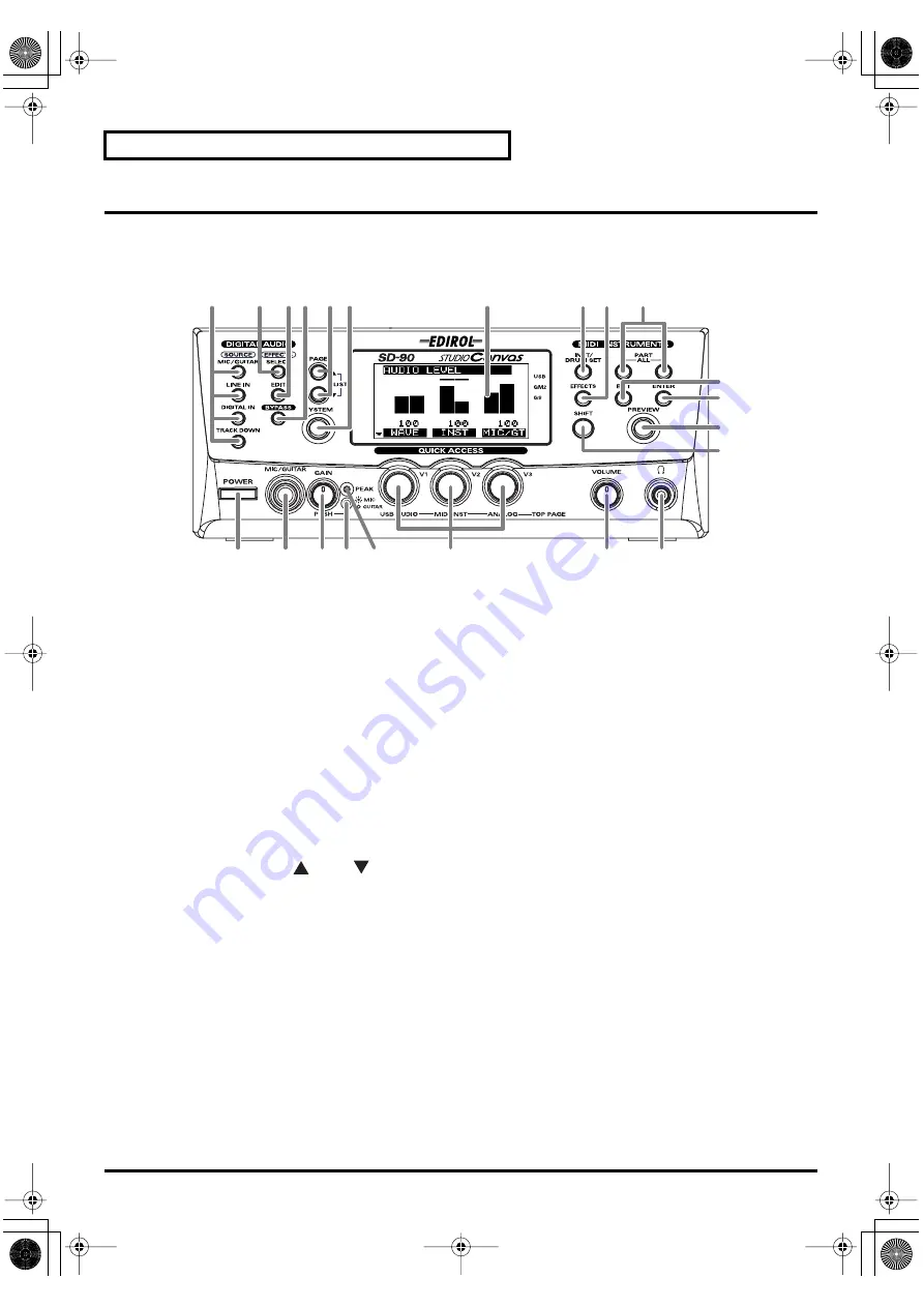
Front Panel


fig.1-01


1

SOURCE Buttons


These buttons recall audio mixer routings suitable for sending the selected input source (input jack) to the 
computer. (


"Selecting a routing"


 (p. 52))


2

SELECT Button


This button selects the type of audio effect (


"Selecting the type of effect (Algorithm)"


 (p. 62)).


3

EDIT Button


This button allows you to edit the parameters of the audio effect (


"Editing the effect"


 (p. 63)).


4

BYPASS Button


This button allows you to temporarily bypass the audio effect so that you can compare the sound with and 
without the effect (


"Editing the effect"


 (p. 63)).


5

PAGE Buttons


When editing the parameters of the audio mixer, use these buttons to switch between screens that consist of 
multiple pages (


"Editing in the List display"


 (p. 54)).

When you press [

] and [

] simultaneously, a list of the parameters will be displayed (


"Editing in the 

List display"


 (p. 54)).


6

SYSTEM Button


Use this button to make settings that affect the entire SD-90 system (


"System-related settings"


 (p. 69)).


7

Display


This shows various types of information (such as level meters or parameter values) related to the current 
state.


8

INST/DRUM SET (Instrument/Drum Set) Button


Use this button to select the instrument (sound) or drum set assigned to each part. (


"Selecting a sound"


 (p. 

24), 


"Selecting a drum set"


 (p. 25))


9

EFFECTS Button


Use this button to select an effect (MFX) for the internal sound generator, or to edit effect parameters (


"About 

the sound generator effects"


 (p. 38)).

3 4

6

7

8 9

10

22

21

20

18 19

17

16

15

1

2

5

11
12

14

13

sd90_manual_e.book 10 ページ 2004年10月4日 月曜日 午後3時28分

Summary of Contents for Studio Canvas SD-90

Page 1: ...house Area DEPO Pf 83 H 2046 Torokbalint HUNGARY TEL 23 511011 AUSTRIA Roland Austria GES M B H Siemensstrasse 4 P O Box 74 A 6063 RUM AUSTRIA TEL 0512 26 44 260 BELGIUM HOLLAND LUXEMBOURG Roland Benelux N V Houtstraat 3 B 2260 Oevel Westerlo BELGIUM TEL 014 575811 EUROPE GREECE STOLLAS S A Music Sound Light 155 New National Road 26422 Patras GREECE TEL 061 435400 IRELAND Roland Ireland Audio Hous...

Page 2: ...ence receptacles and the point where they exit from the apparatus 11 Only use attachments accessories specified by the manufacturer 13 Unplug this apparatus during lightning storms or when unused for long periods of time 14 Refer all servicing to qualified service personnel Servicing is required when the apparatus has been damaged in any way such as power supply cord or plug is damaged liquid has ...

Page 3: ...vel that is uncom fortable If you experience any hearing loss or ringing in the ears you should immediately stop using the unit and consult an audiol ogist 011 Do not allow any objects e g flammable material coins pins or liquids of any kind water soft drinks etc to penetrate the unit 013 In households with small children an adult should provide supervision until the child is capable of following ...

Page 4: ...ects on the unit 107b Never handle the power cord or its plugs with wet hands when plugging into or unplugging from an outlet or this unit 108a Before moving the unit disconnect the power plug from the outlet and pull out all cords from external devices 109a Before cleaning the unit turn off the power and unplug the power cord from the outlet 110a Whenever you suspect the possibility of lightning ...

Page 5: ...phones so you do not need to be concerned about those around you especially when it is late at night 559a When you need to transport the unit package it in the box including padding that it came in if possible Otherwise you will need to use equivalent packaging materials 562 Use a cable from Roland to make the connection If using some other make of connection cable please note the following precau...

Page 6: ... sets 18 About parts and sounds 19 Different types of part 19 Polyphony and voices 19 Switching the sound generator mode 20 Selecting a part 21 Selecting the type of part INST DRUM 22 Selecting the sound set 23 Selecting a sound 24 Selecting a drum set 25 Muting soloing a part 26 Muting a part 26 Soloing a part 27 About parameters 28 Editing the parameters 29 Editing part parameters 29 Editing in ...

Page 7: ...ing in the List display 54 Audio mixer parameter list 55 About the routing presets 57 Basic routing 57 Record the dry sound Default Source Recording 57 Apply effects and track down 58 Insert effects and track down 58 Apply effects to each channel and record 58 Apply effects and record a single channel 59 Monitor the effect while recording only the dry sound 60 Using the audio effects 61 Select the...

Page 8: ...e SD 90 via MIDI 77 Controlling the internal sound generator 77 Switching the sound generator mode 77 Switching the sound set 79 Switching the type of part 80 Switching sounds 82 Switching the drum set 85 Editing MIDI effect parameters 87 Writing loading SD 90 settings 93 Controlling the audio mixer 95 Switching the routing 95 Editing mixer parameters 95 Editing audio effect parameters 96 Appendic...

Page 9: ...plementary explanations for a function or tips for operation If the SD 90 does not operate as you expect refer to Troubleshooting p 97 Main features Richly expressive pro quality sounds The 32 part 128 voice MIDI sound generator section features three MFX multi effect units in addition to reverb chorus and equalizer More than a thousand sounds using pro quality wave data are organized into four ca...

Page 10: ...ttons to switch between screens that consist of multiple pages Editing in the List display p 54 When you press and simultaneously a list of the parameters will be displayed Editing in the List display p 54 6 SYSTEM Button Use this button to make settings that affect the entire SD 90 system System related settings p 69 7 Display This shows various types of information such as level meters or parame...

Page 11: ...ning this knob will adjust the gain of the signal input from the MIC GUITAR jack or LINE IN jacks By pressing this knob you can select whether a mic or a guitar is connected to the MIC GUITAR jack Connecting a mic guitar p 49 18 GAIN Indicator This indicates whether mic or guitar is selected for the MIC GUITAR jack Mic is selected when the indicator is lit and guitar is selected when the indicator...

Page 12: ...coaxial cable with COAXIAL and an optical cable with OPTICAL OUT These jacks send digital signals to other digital devices Use a coaxial cable with COAXIAL and an optical cable with OPTICAL 4 OUTPUT Jacks These jacks output audio signals to your audio playback system or amplified speakers 1 These jacks always output the signals that are being input at the input jacks Use the front panel VOLUME kno...

Page 13: ... which applies effects to all audio sources Using the audio effects p 61 Routes to the computer via USB connector OUTPUT jacks Digital OUT jack MIDI messages from the USB connector Audio signals from the USB connector MIC GUITAR LINE IN Audio Mixer MIDI sound generator Audio effects Digital IN jack SD 90 Adjusting the volume in the main screen In the main screen the screen that appears immediately...

Page 14: ...ob fully counterclockwise minimum setting 2 Press SYSTEM fig 2 05a 3 Press PAGE to get the screen shown at right to appear fig 2 05b 4 Press ENTER and the demo song will begin playing Slowly turn the VOLUME knob clockwise to adjust the volume to a comfortable level Once the demo song has played to the end it will automatically be played over again starting from the beginning 5 Press EXIT to stop t...

Page 15: ...urn the V1 knob the capital sound will change When you turn the V2 knob the variation sound will change Try selecting various sounds and listening to the phrases 4 Press INST DRUM SET once again to return to the main screen 1 4 3 2 Changing the Preview settings At the factory settings you can audition a characteristic phrase that uses the currently selected sound Phrase Preview Alternatively you c...

Page 16: ...2 Press PAGE or PAGE until LCD Contrast is displayed 3 Turn the V3 knob to adjust the contrast of the display fig 2 03 LCD Contrast 1 5 8 Adjusts the contrast of the display fig 7 1ga LCD Mode Normal Invert Adjusts the contrast of the display 4 Press ENTER The contrast setting you specify will be remembered by the SD 90 Do not turn off the power while the setting is being stored while TBD is displ...

Page 17: ...nded specifications of GM2 Native mode This is the sound generator mode that allows you to take advantage of the SD 90 s full potential It uses the same instrument files and sound sets as GM2 mode and provides a greater number of editable parameters In addition it provides two special sound sets that collect the most distinctive of the sounds of the SD 90 GS mode This sound generator mode supports...

Page 18: ...ese sounds The set also includes acoustic instruments with a clear upper register produced by equalization processing and synth sounds based on multi effects Up to three enhanced sounds can be used simultaneously This set also contains some sounds that do not use MFX Special This sound set can be used only in Native mode It consists mainly of the best sounds of the SD 90 from the Enhanced set and ...

Page 19: ...ode By default the following part mode is selected for each part Polyphony and voices Each of the SD 90 s sounds consist of units called voices There is a limit to the number of voices that can be used and the SD 90 is able to use 128 voices simultaneously Some sounds instruments use more than one voice Instrument list GM2 Native mode p 129 The main reason that an instrument uses some voices is so...

Page 20: ...the sound generator mode fig 5 02 1 Press SYSTEM fig 7 01a_67 2 2 Turn the V1 knob to select the desired sound generator mode GM2 Native GS XGlite fig 5 02a 3 Press ENTER You will switch to the sound generator mode you selected in step 2 The current sound generator mode is indicated in the right side of the display If none of the modes has a symbol displayed by it Native mode is selected 4 Press S...

Page 21: ...it fig 5 03 1 Press INST DRUM SET fig 5 03a_67 2 2 Press PART or PART to select the part to be edited The number of the part currently being edited is indicated at the bottom of the display 3 Press INST DRUM SET once again to return to the main screen 1 3 2 sd90_manual_e book 21 ページ 2004年10月4日 月曜日 午後3時28分 ...

Page 22: ...e for each part fig 5 04 1 Press INST DRUM SET 2 Press PAGE once fig 5 04a_67 2 3 Turn the V1 knob to select the desired part mode INST or DRUM The part mode has now been selected fig 5 04b_67 2 4 Press INST DRUM SET once again to return to the basic screen 3 2 1 4 sd90_manual_e book 22 ページ 2004年10月4日 月曜日 午後3時28分 ...

Page 23: ...sets fig 5 05 1 Press INST DRUM SET fig 5 05a_67 2 2 Turn the V3 knob to select the desired sound set CLASIC Classical CONTEM Contemporary SOLO Solo ENHANC Enhanced SP 1 Special 1 Native mode only SP 2 Special 2 Native mode only The sound set has now been selected 3 Press INST DRUM SET once again to return to the main screen 2 1 3 sd90_manual_e book 23 ページ 2004年10月4日 月曜日 午後3時28分 ...

Page 24: ...By changing the MIDI bank number of these sounds you can select variations that have a different tonal character These are called variation sounds For details on the various sounds that can be selected refer to Instrument list GM2 Native mode p 129 fig 5 06 1 Press INST DRUM SET fig 5 06a_67 2 2 Turn the V1 knob or V2 knob to select the sound The sound name instrument shown in the center of the di...

Page 25: ...ST DRUM p 22 For details on the drum sets that are available refer to Instrument list GM2 Native mode p 129 Drum sets do not have variation sounds fig 5 07 1 Press INST DRUM SET fig 5 07a_67 2 2 Turn the V1 knob to select a drum set The INST number in the display will change and the drum set name shown in the center of the display will also change 3 Press INST DRUM SET once again to return to the ...

Page 26: ...ated for that part and it will be set to Solo Even if you subsequently cancel Solo that part will not return to Mute If you want to mute that part once again use the procedure described in Muting a part Muting a part fig 5 08 1 Press INST DRUM SET 2 Press PART or PART to select the part that you want to mute fig 5 08a_67 2 3 When you hold down SHIFT and press PART the part you selected in step 2 w...

Page 27: ...ig 5 09 1 Press INST DRUM SET 2 Press PART or PART to select the part that you want to solo fig 5 09a 3 Hold down SHIFT and press PART to solo the part you selected in step 2 Solo will be defeated when you press SHIFT PART once again Parts other than the soloed part will not sound nor will the bar graph be displayed 4 Press INST DRUM SET once again to return to the main screen 1 4 2 3 sd90_manual_...

Page 28: ...e included CD ROM The adjustable range of each parameter is printed in this manual as described in the comment column of the MIDI implementation Internal operation of parameters When you select a sound the sound data is loaded into a memory location called the temporary area The SD 90 produces sound based on the data in this temporary area fig 5 14 When you edit a sound or drum set you are tempora...

Page 29: ...cter and pitch fig 5 10 1 Make sure that the sound generator mode is set to either GM2 or Native If GM2 or Native is not selected refer to Switching the sound generator mode p 20 2 Press INST DRUM SET 3 Select the part and sound as described in the procedures for Selecting a part p 21 and Selecting a sound p 24 fig 5 10a_67 2 4 After you have selected the part and sound press PAGE or PAGE to acces...

Page 30: ...INST DRUM SET fig 5 11a_67 2 2 Simultaneously press PAGE and PAGE The parameters will be displayed in a list 3 In this state you can turn the V1 knob to select the parameters that you want to edit When you turn the V3 knob the value of the selected parameter highlighted will change 4 Once again press PAGE and PAGE simultaneously to return to the icon display 2 4 1 3 sd90_manual_e book 30 ページ 2004年...

Page 31: ...s for all parts fig 5 12a_67 2 2 Turn the V1 knob to select the parameter that you want to edit e g Master Volume 3 Turn the V3 knob to adjust the value of the parameter you selected in step 2 4 If you want to keep the results of your edit hold down SHIFT and press ENTER after step 3 The current setting will be transmitted from the USB connector USB mode p 71 or the MIDI OUT connector MIDI mode p ...

Page 32: ...cifies the depth of vibrato Volume cc 7 0 100 127 Adjusts the volume of each part Increasing this value will make the sound louder The overall volume of the entire SD 90 is adjusted by the VOLUME knob If the VOLUME knob is set to the minimum position there will be no sound even if you raise this level parameter Pan cc 10 L64 0 63R Adjusts the pan localization of the sound image effective when ster...

Page 33: ...e the sound brighter or darker The cutoff frequency will also change over time according to an envelope By adjusting the filter and envelope you can create sounds that have movement and expression fig p8 1j TVF Resonance cc 71 64 0 63 Increasing the resonance value will emphasize the harmonics in the region of the cutoff frequency giving a distinctive character to the sound For some sounds negativ...

Page 34: ... the cutoff frequency If the cutoff frequency is lowered it will rise as the envelope rises and fall as the envelope falls TVF TVA Release cc 72 64 0 63 This adjusts the time from when you release the key note off message until the sound decays to silence The cutoff frequency will also fall accordingly TVF TVA Attack cc 73 64 0 63 This adjusts the sharpness with which the note begins TVF TVA Decay...

Page 35: ...he pitch and negative settings will lower the pitch By setting two or more parts to the same MIDI channel and instrument and using Fine Tune to slightly spread apart the pitch of each part you can play these parts together to create rich and spacious sounds To adjust the pitch of all parts together edit the Master Fine Tune setting p 37 Coarse Tune Channel Coarse Tuning 64 0 63 The Channel Coarse ...

Page 36: ...ich playing dynamics will affect the volume and cutoff frequency Part Keyboard Fade Width Lower 0 127 This specifies how the volume will change when you play notes that are outside the lower limit of the part s key range With higher settings of this parameter the volume will decrease gradually If you want there to be no sound at all when you play below the specified key range set this to 0 Part Ke...

Page 37: ...90 to the tuning of another instrument you can adjust the Master Tuning in a range from 415 3 Hz to 466 2 Hz The displayed value for example 440 0 Hz is the frequency of the A4 note note number 69 Master Coarse Tuning 24 0 24 This parameter transposes the pitch of all parts in semitone steps For example when using your sequencer software to play song data this parameter can be adjusted to change t...

Page 38: ...an effect that boosts or cuts the level of specific frequency bands of the sound modifying its tonal character Multi effect Multi effect provides 90 different effect types These include single effects such as distortion and delay as well as multiple types that combine two or more effects Chorus and reverb are additionally provided as multi effect effect types but you can also use the separate chor...

Page 39: ...ound generator mode p 20 2 Press EFFECT The sound generator Effect Edit screen will appear 3 Press PART or PART to access either the Reverb Chorus or MFX page MFX cannot be selected if the sound generator mode is GM2 mode 4 Turn the V1 knob to select the parameter that you want to edit it will be highlighted 5 Turn the V3 knob to modify the value of the parameter you selected in step 4 This comple...

Page 40: ...his reverb simulates the reverberation of a room It produces a crisp and spacious re verberation Medium Room Large Room Medium Hall This reverb simulates the reverberation of a hall It produces a deeper sensation than Room Large Hall Plate This simulates a plate echo a reverb unit that uses the vibration of a metal plate Type Default setting Reverberation time seconds Small Room 44 1 1 Medium Room...

Page 41: ...amount that is sent to reverb EQ Equalizer You can make equalizer settings for the output of the sound generator section EQL Left channel Lch EQR Right channel Rch EQ Switch Off On Switches the equalizer on off EQ1 Low Frequency 200 400 Hz EQ2 Low Frequency 200 400 Hz Specify the frequency at which the low range will be adjusted EQ1 Low Gain 15 15 EQ2 Low Gain 15 15 Specify the gain amount of boos...

Page 42: ...of the reverb When the Type is DELAY or PAN DELAY this specifies the delay time Increasing this value will produce a more spacious feeling HF Damp Reverb Delay HF Damp Specifies the frequency above which the high frequency component of the reverb sound will be cut Lowering this value will cause a greater portion of the high frequency range to be cut producing a softer toned reverb sound If no cutt...

Page 43: ...600 2000 2500 3200 4000 5000 6400 8000 10000 12500 Hz BYPASS Density Reverb Density 0 127 Adjusts the density of the reverb sound Higher settings will produce a denser sound Diffusion Reverb Diffusion 0 127 Adjusts the way in which the density of the reverb sound will change over time With higher settings of this parameter the sound will become denser as time passes The effect of this parameter is...

Page 44: ...e is 1 CHORUS Rate Chorus Rate 0 05 10 00 Hz Specifies the frequency at which the chorus sound will be modulated Depth Chorus Depth 0 127 Specifies the depth to which the chorus sound will be modulated Feedback Chorus Feedback 0 127 Specifies the amount of chorused sound that will be returned fed back to the input of the chorus Increasing this value will produce a more complex chorus effect Phase ...

Page 45: ...es the amount of feedback Changing the amount of feedback will change the number of times that the delay will repeat Negative settings will invert the phase of the feedback sound Center Delay Center Level 0 127 Specifies the level of the delay sound localized at the center Left Delay Left Level 0 127 Specifies the level of the delay sound localized at the left Right Delay Right Level 0 127 Specifi...

Page 46: ...d of a specific part you must do the following two things Select the location source of the parameters used by MFX Send the output of the part to MFX Select the location of the parameters used by MFX MFX A SOURCE MFX A source COMMON PART 1 32 MFX B SOURCE MFX B source COMMON PART 1 32 MFX C SOURCE MFX C source COMMON PART 1 32 MFX parameters e g algorithm reverb type distortion type exist both wit...

Page 47: ...u want to use sounds from the Enhanced set for other parts in Native mode perform the following steps Example Using MFX A for part 4 1 Set the MFX A Source to PART4 This allows the MFX A effect to be applied with the settings of the sound that is called up for part 4 2 Set the Part 4 Output Assign to PATCH This selects PATCH as the output destination for the part Since the output setting of an Enh...

Page 48: ...ish to refer to this block diagram for a general understanding of the audio mixer Connecting an input source audio device Analog connections You can connect a mic guitar CD player or other device to the analog input jacks on the front panel and rear panel Before making connections to other devices you must turn down the volume of all devices to prevent malfunction and or speaker damage Selecting a...

Page 49: ... GAIN knob so that the GAIN indicator lights If you are connecting a guitar press the GAIN knob so that the GAIN indicator goes dark If the GAIN indicator is dark when a mic signal is being input the audio from the mic will be too weak since the MIC GUITAR jack will be functioning as a guitar input 3 Connect your mic or guitar to the front panel MIC GUITAR jack The MIC GUITAR jack is not compatibl...

Page 50: ...N jack It is not possible to use both types of jack simultaneously When making digital connections you must also make sure that the sampling frequency of the connected recorder the sampling frequency of the SD 90 and the sampling frequency of the audio handled by the sequencer program on your computer are all set to the same setting Use the following procedure to select the type of digital jack an...

Page 51: ...from an audio CD to MD or DAT is permitted For example once you have made a digital copy to an MD it will not be possible to digitally copy that MD onto another MD This is because an audio CD contains in addition to the audio data flags that prohibit digital copying In contrast the signal that is output from the SD 90 s DIGITAL OUT jacks will allow more than one generation of digital copying Howev...

Page 52: ...p 57 If the selected routing is one that uses an audio effect No 05 18 the source will be output with the effect applied When the power is turned on the effect type is Space Multi Selecting a routing In order to record audio signals on your sequencer software select a routing that sends the sound from the SD 90 via the USB cable to your computer fig 3 06 fig 3 07 1 Press one of the SOURCE buttons ...

Page 53: ... output to the OUTPUT 1 jacks The volume of each source can be adjusted in two ways icon display or list display Use the method appropriate for your situation or preferences It is not possible to save the edited state of the audio mixer in the SD 90 s internal memory The edited state will be lost when you turn off the power If you want to preserve the edited state either make a note of the setting...

Page 54: ... Press PAGE or PAGE until the parameter you want to edit is displayed fig 3 09 3 To edit the settings turn the knob V1 V3 for the parameter you want to edit 4 Once again press the SOURCE button you pressed in step 1 to return to the main screen Editing in the List display fig 3 10 1 Press one of the SOURCE buttons according to the input source you want to use The button will light indicating that ...

Page 55: ...STER master volume 0 127 Output level from OUTPUT 1 jacks Knob Display Name Range Explanation Example screen V1 A Vol analog volume 0 100 127 Volume of the an alog input jacks V2 A Muted analog mute OFF ON Mute on off for the analog input jacks V3 A Send analog send level 0 64 127 Send level from the analog input jack to effects Knob Display Name Range Explanation Example screen V1 D Vol digital v...

Page 56: ... to the effects V3 INST Mute in strument mute 0 64 127 Mute on off for internal sound generator List display In the list the parameters are shown in the following order fig 3 11 Record Volume Master Volume Analog Volume Analog Mute Analog Send Level Wave Volume Wave Mute Wave Send Level Digital Volume Digital Mute Digital Send Level Inst Volume Inst Mute Inst Send Level Rec Monitor Sw Mixer Mute O...

Page 57: ...se routings when you want the input signal to be recorded into your computer without being processed No Type Display Connections 00 Mix all input sources and record them Default No Type Display Connections 01 Record from the analog jacks Default Ana Rec 02 Record from the digital jacks Default Dig Rec 03 Record from the USB con nector Default Wav Rec 04 Record the output of the internal sound gene...

Page 58: ...to each channel and record These routings let you insert an effect only into the input source you want to record mix all input sources and send the result to your computer The output level of the audio effect will determine the volume of the source processed by the effect For example you can use one of these routings when you want to apply an effect guitar multi to the guitar input mix it with the...

Page 59: ... an effect into the in ternal sound generator output and record the mix Ins Syn Mix Rec No Type Display Connections 11 Insert an effect into the an alog input and record it Ins Ana Src Rec 12 Insert an effect into the digital input and record it Ins Dig Src Rec 13 Insert an effect into the USB input and record it Ins Wav Src Rec 14 Insert an effect into the output of the internal sound generator a...

Page 60: ...tor the overall sound including the backing and record only the unprocessed source No Type Display Connections 15 Insert an effect into the an alog input and record the dry sound Ins Ana Dry Rec 16 Insert an effect into the digital input and record the dry sound Ins Dig Dry Rec 17 Insert an effect into the USB input and record the dry sound Ins Wav Dry Rec 18 Insert an effect into the output of th...

Page 61: ...erator You can also apply an effect to the input source and send the result to your computer recording wet or monitor the processed sound while recording only the unprocessed dry sound The general procedure for using an audio effect is shown below Select the location of the effect Select the effect algorithm Edit the effect Select the location of the effect Mixer Routing The location of the audio ...

Page 62: ...iately If you have selected a mixer routing preset 00 04 that does not use the audio effect no effect will be applied Selecting a routing p 52 However the internal algorithm itself will change For some effects such as distortion and lo fi the output level may be high even though the source level is low Before you switch effects turn down the VOLUME knob to prevent damage to your speakers and retur...

Page 63: ...ble to save the edited state of the effect in the SD 90 s internal memory The edited state will be lost when you turn off the power If you want to preserve the edited state either make a note of the settings or save them on an external MIDI sequencer or similar device Writing loading SD 90 settings p 93 Editing in the icon display fig 4 03 1 Press EDIT The parameters of the currently selected algo...

Page 64: ...Turn the V3 knob VALUE to edit the setting 5 Press EDIT once again to return to the main screen Bypassing the effect fig 4 07 fig 4 08 1 If you want to compare the sound processed by the effect with the unprocessed sound press BYPASS The BYPASS button will light and the effect block will be highlighted indicating that the effect has been bypassed 2 When you press BYPASS once again BYPASS will go d...

Page 65: ...hing from mild overdrive to extreme distortion fig 4 10 Vocal Bass Multi This algorithm is suitable when recording vocals or bass through a mic It provides a compressor to make the volume more consistent a noise suppressor to remove unwanted noise and delay and chorus to add spatial resonance By using the lo fi processor you can simulate a lo fi sound making it sound as if the source were recorded...

Page 66: ...ng the input level may cause the output level to suddenly become very loud Before you adjust the lo fi processor it is best to turn down the volume to prevent speaker damage and then adjust the level appropriately while listening to the result fig 4 15 Surround RV Surround Reverb This is a reverb effect that uses Roland s RSS technology to provide multi speaker surround output four speakers It exp...

Page 67: ...kers Using surround output fig 4 17 When surround reverb is used it may be easier for the output to become distorted Watch the level meters shown in the display and make adjustments so that the levels of the audio and the internal sound generator are appropriate 1 Press SYSTEM 2 Press PAGE or PAGE until Select Output 2 is displayed fig dummy fig 4 18 3 Turn the V1 knob to select the output for the...

Page 68: ...ut 2 back to INST Mastering This effect divides the source into frequency bands high and low and makes the volume more consistent and improves the balance By using this effect when you mixdown to MD or DAT or when mixing to an audio file WAV file you can master the sound at an optimal level fig 4 19 Output2 Auto Inst Rear Other than Surround Reverb Effect not used INST INST Effect used INST INST S...

Page 69: ...value of the item in the third line of the display The value of the most recently selected item will be highlighted Here s the basic procedure for setting these parameters 4 When you have selected the desired value press ENTER If you decide not to change the value press EXIT 5 Press SYSTEM once again to return to the main screen Dis play V1 V2 V3 1 INST Init Bulk Dump INST Bulk Dump Audio 2 MIDI S...

Page 70: ...k dump you can also set the parameters of two SD 90 units to identical settings By sending individual data you can quickly and easily create data e g for a sequencer without having to look up each system exclusive message Bulk Dump INST A01 A16 B01 B16 fig 7 1ab Specifies the internal sound generator parameters that you want to transmit when the bulk dump is executed Bulk Dump INST can be carried ...

Page 71: ...ou connect the SD 90 to your computer via USB you will not necessarily be able to use all 32 parts Please carefully read the owner s manual for your sequencer software MIDI mode fig 7 3 The MIDI messages received at the MIDI IN connectors will be passed directly to the internal sound generator The SD 90 has two MIDI IN connectors and each MIDI IN connector can receive data for 16 Parts In MIDI mod...

Page 72: ...e ID number The device ID number is a number from 1 to 32 The factory setting is 17 SysEx DevID 17 32 fig 7 1bc Specifies the device ID number used when the sound generator mode is Native mode When playing SMF music files produced by Roland Edirol you must set the device ID number to 17 Playback will not be correct if this is not set to 17 It is not possible to specify a different device ID number...

Page 73: ...er to the MIDI OUT connectors 1 and 2 will no longer be output i e they will not be merged On the other hand turning this On when operating in MIDI mode will cause the MIDI messages input at the MIDI IN 1 connector to be thru ed to the MIDI OUT 1 connector as well as being sent to PART A and the MIDI messages input at the MIDI IN 2 connector to be thru ed to the MIDI OUT 2 connector as well as bei...

Page 74: ... played with high quality and stable timing You should select Vendor when using 24 bit capable applications such as the Cakewalk series and Cool Edit or when using ASIO compatible applications that are able to record play edit high quality audio such as Cubase VST Logic Audio and SingerSongWriter Generic In the future you should be able to use the USB audio driver included with the operating syste...

Page 75: ...ound Reverb as the audio effect algorithm the rear speaker sound will be output INST The sound of the internal sound generator will always be output REAR The sound of the audio effect will always be output If an algorithm other than Surround Reverb is being used no sound will be output About recording via a digital connection One generation of digital copying recording from an audio CD to MD or DA...

Page 76: ...he contrast darkness of the SD 90 s display Increasing this value will darken the characters in the display fig 7 1ga LCD Mode Normal Invert Allows you to chose the desired display mode for the LCD Setting the system tempo fig 7 1h System Tempo 20 120 250 This sets the tempo of the entire SD 90 system When you set the Delay Time of an internal sound generator effect MFX to Clock Tempo it will foll...

Page 77: ...etail Although this mode lets you control parameters that cannot be edited in other modes operations in Native mode are not compatible with GM2 In other words song data created in Native mode cannot be reproduced by playing it back on another GM2 sound generator fig 5 01b In Native mode MFX and sounds instruments can be handled independently For this reason simply selecting an Enhanced sound will ...

Page 78: ...rt parameters at the beginning of the song Transmit a program change number during the song to switch to sound B The structure of the synthesizer When controlling the sound parameters it is important to understand the structure of a conventional music synthesizer oscillator TVF TVA envelope LFO We recommend that you understand the following concepts before you use the operations described in this ...

Page 79: ... switch and nn selects the sound set Switching the sound set in Native mode In Native mode you can switch the sound set by transmitting a Bank Select message The upper byte MSB of the MIDI bank number will switch the sound set MIDI bank number CC 00 MSB The set will be switched according to the value you insert here decimal 80 50H Special 1 set 81 51H Special 2 set 96 60H Classical set 97 61H Cont...

Page 80: ...4 60H Classical set 105 61H Contemporary set 106 62H Solo set 107 63H Enhanced set Switching the Part Mode in GS mode In GS mode the Inst mode and Drum Part are normally set as follows Inst part Part 1 9 11 16 Drum part Part 10 fig 5 2aj Transmit system exclusive data to switch the Part Mode Address 40 1 15 Part number Data 00 02 00 Normal 01 Drum1 02 Drum2 Checksum For details on the calculation ...

Page 81: ... F0 43 10 4C 00 00 7E 00 F7 and then use a Bank Select message to select the sound Switching sounds p 82 Correspondence between actual parts and part numbers in GS mode Actual part Part number Actual part Part number Part1 1 Part9 9 Part2 2 Part10 0 Part3 3 Part11 A Part4 4 Part12 B Part5 5 Part13 C Part6 6 Part14 D Part7 7 Part15 E Part8 8 Part16 F sd90_manual_e book 81 ページ 2004年10月4日 月曜日 午後3時28分...

Page 82: ... name of the sound Example Native mode instrument list fig 4 7 PC Instrument number program number LSB Variation number value of controller number 32 Capital sounds variation number 0 are printed in bold type MSB Sound set number value of controller number 0 Classic Set Sound set Classical set sounds Contemp Set Sound set Contemporary set sounds Solo Set Sound set Solo set sounds Enhance Set Sound...

Page 83: ...mber 009 Switching sounds in GS mode Transmit bank select MSB and program change Leave the bank select LSB set at 0 Actual transmission of MIDI messages When you input MIDI messages into sequencer software on your computer for transmission to the SD 90 send the messages in the following order 1 Value of control change 0 MIDI bank number MSB variation number 2 Value of control change 32 MIDI bank n...

Page 84: ...to 017 Organ 1 variation 000 transmit the following MIDI CH 02 CC 00 000 set the variation number to 000 CC 32 0 PC 017 set the instrument number to 017 Example Changing the variation of the part s sound To switch the sound of part 1 to 008 Detuned EP1 variation 008 transmit the following MIDI CH 01 CC 00 008 set the variation number to 008 CC 32 0 PC 006 set the instrument number to 008 Example C...

Page 85: ...me sound as percussion instrument sound of Standard Set 1 PC001 Note number for which no percussion instrument exists Switching drum sets in GM2 mode Transmit bank select LSB CC 32 and program change PC Bank select MSB CC 00 is used to switch the part mode Inst part and Drum part correspond to the following numbers Example Specifying part 10 as a GM2 drum part 009 Room Set 2 MIDI CH 10 CC 00 120 s...

Page 86: ...rt MIDI receive channel 10 The note data in the rhythm data you are playing must match the note numbers of the drum set you are using fig 4 11e Example Switching the drum set Transmit the following to set part 10 sound to 009 Room MIDI CH 10 CC 00 000 specify variation number 000 CC 32 0 PC 009 specify drum set number 009 Room Inst part Drum part 80 50H Special 1 set 81 51H Special 2 set 96 60H Cl...

Page 87: ...rus via MIDI messages transmit the following system exclusive data global parameter control F0 7FH 10 04 05 01 01 01 01 02 pp vv F7 pp Parameter number vv Value setting Example Setting the chorus type to 3 Chorus4 Transmit the following system exclusive data F0 7F 10 04 05 01 01 01 02 01 00 03 F7 VV setting pp 0 Reverb Type 00 Small Room 01 Medium Room 02 Large Room 03 Medium Hall 04 Large Hall 08...

Page 88: ...enhanced sounds selected for parts 1 3 can be used by other parts The output of all parts that use that MFX will be mixed and sent to the MFX Do not change the MFX source of the three insertion effects after a Native Reset message is received This will not work if effect type 00 no effect THROUGH has been specified for the enhanced sounds selected for parts 1 3 Any control performed on the MFX wil...

Page 89: ... ignored fig 8 08_99 1 Make the MFX use the settings of the multitimbre common to all parts Address mm when you want to use MFX A from multiple parts 30 when you want to use MFX B from multiple parts 31 when you want to use MFX C from multiple parts 32 Data 01 MFX Source COMMON Checksum ss For details on the calculation method refer to Calculating the checksum in MIDI implementation MIDIImple_E pd...

Page 90: ...t Select the effect type 00 5A Checksum ss For details on the calculation method refer to Calculating the checksum in MIDI implementation MIDIImple_E pdf on the included CD ROM Example Share MFX B with the sounds of parts 4 6 and 7 and set the effect type to 24 REVERB 1 F0 41 10 00 48 12 10 00 00 31 00 3F F7 2 1 F0 41 10 00 48 12 10 00 23 1F 00 2E F7 2 2 F0 41 10 00 48 12 10 00 25 1F 00 2C F7 2 3 ...

Page 91: ... 11 when editing parameter number 2 06 15 the address will increment 04H each time the parameter number increases by 1 when editing parameter number 29 07 01 when editing parameter number 30 07 05 when editing parameter number 31 07 09 when editing parameter number 32 07 0D Data d1 d2 d3 d4 Effect parameter The lower 4 bits of the four data bytes indicate a signed numerical value Checksum ss For d...

Page 92: ...parameter number 29 07 01 for MFX B 09 11 for MFX C 0B 11 when editing MFX A s parameter number 30 07 05 when editing MFX A s parameter number 31 07 09 when editing MFX A s parameter number 32 07 0D Data d1 d2 d3 d4 Effect parameter The lower 4 bits of the four data bytes indicate a signed numerical value For details on the data byte expression refer to Data byte expression p 91 Checksum ss For de...

Page 93: ...ll explain how to transmit a bulk dump from the SD 90 fig 8 3 1 Press SYSTEM 2 Turn the V2 knob or V3 knob to select the contents of the data that will be transmitted The highlighted data will be transmitted Bulk Dump INST can be executed only when the sound generator is in Native mode In other cases this will be displayed as and cannot be executed fig 7 1aa_67 2 Bulk Dump INST A01 A16 B1 B16 Spec...

Page 94: ...ftware or external MIDI sequencer you can restore the SD 90 to the state in which it was when the data was saved Transmitting individual data Individual data can be transmitted in each editing screen fig 8 3a 1 In each editing screen select the parameter that you want to transmit and specify its value 2 Hold down SHIFT and press ENTER The highlighted parameter value will be transmitted 2 sd90_manu...

Page 95: ...xer parameters To edit the recording volume Rec Vol of the audio mixer via MIDI transmit the following system exclusive data Example Setting the audio mixer recording volume to 89 fig 9 74b_99 Transmit the following system exclusive data F0 41 10 00 48 12 a1 a2 a3 a4 dd ss F7 1 2 3 4 5 6 7 8 9 1 Exclusive status 2 ID Roland 41H 3 Device ID 4 Model ID SD 90 00H 48H 5 Command ID Data set 12H 6 Addre...

Page 96: ...ti and set the effect parameter to 89 The lower 4 bits of the four data bytes indicate a signed numerical value For details on the data byte expression refer to Data byte expression p 91 fig 9 74e_99 3 Transmit AFX SW to turn on the audio effect F0 41 10 00 48 12 02 10 20 00 20 2E F7 1 2 3 4 5 6 7 8 9 Audio AFX Type 20H 32 Audio Common F0 41 10 00 48 12 02 10 20 29 08 00 05 09 4C F7 1 2 3 4 5 6 7 ...

Page 97: ...og input jacks the GAIN knob may have been lowered Setting the volume of the source sound p 53 A specific part cannot be heard Make sure that the MIDI receive channel of the Part matches the MIDI transmit channel of the connected MIDI device There is a part that does not sound even when you press the PREVIEW button Is the part soloed or muted Muting a part p 26 Soloing a part p 27 A certain range ...

Page 98: ...en p 13 The volume level may have been lowered by an expression pedal or similar device connected to a connected MIDI device Are the audio routing settings correct Refer to Selecting a routing p 52 and check the settings If there is still no sound it is possible that there is a problem with the driver or software settings Refer to Troubleshooting in the Getting Started manual and check the appropr...

Page 99: ... the included CD ROM The SD 90 does not transmit MIDI data If you want to transmit SD 90 data via the USB connector start up the SD 90 in USB mode MIDI data will not be output from the USB connector if the SD 90 is started up in MIDI mode Selecting the startup mode p 70 If you switch on MIDI IN THRU when the SD 90 has been started up in USB mode it will no longer be possible to use the external MI...

Page 100: ...mitting a bulk dump p 93 Transmitting individual data p 94 In some cases depending on the environment in which the unit is installed the surface of the panel may sometimes feel rough and grainy This is due to an infinitesimal electrical charge which is absolutely harmless However if you are concerned about this connect the ground terminal p 12 with an external ground When the unit is grounded a sl...

Page 101: ... 1 16 OFF PitchBendSens Pitch Bend Sensitivity 0 24 Modulation Depth Modulation Depth 0 127 Scale Octave Tuning Adjust Scale Octave Tuning Adjust 64 0 63 Part parameters Native mode Parameter Value Legato ON OFF Legato ON OFF ON OFF Part Velocity Sens Offset Part Velocity Sens Offset 63 0 63 Part Keyboard Fade Width Lower Part Keyboard Fade Width Lower 0 127 Part Keyboard Range Lower Part Keyboard...

Page 102: ...on Rate 0 127 Mod Depth Modulation Depth 0 127 Feedback Feedback 0 127 Send to Reverb Send to Reverb 0 127 EQ Equalizer Parameter Value EQ Switch EQ Switch Off On EQL Low Frequency EQL Low Frequency 200 400Hz EQR Low Frequency EQR Low Frequency 200 400Hz EQL Low Gain EQL Low Gain 15 15 EQR Low Gain EQR Low Gain 15 15 EQL High Frequency EQL High Frequency 2000 4000 8000Hz EQR High Frequency EQR Hig...

Page 103: ...Frequency 5 LF Damp Gain LF Damp Gain 36 0 dB HF Damp Freq HF Damp Frequency 6 HF Damp Gain HF Damp Gain 36 0 dB 4 160 200 250 320 400 500 640 800 1000 1250 1600 2000 2500 3200 4000 5000 6400 8000 10000 12500 Hz BYPASS 5 50 64 80 100 125 160 200 250 320 400 500 640 800 1000 1250 1600 2000 2500 3200 4000 Hz 6 4000 5000 6400 8000 10000 12500 Hz Chorus System Effect Parameter Value Chorus Type Chorus...

Page 104: ...e MFX A C Control 1 4 Source OFF CC01 95 PITCH BEND AFTERTOUCH SYS CTRL 1 4 MFX A C Control 1 4 Sens MFX A C Control 1 4 Sensitivity 63 63 MFX A C Parameter 1 32 MFX A C Parameter MFX A SOURCE MFX A source COMMON PART1 32 MFX B SOURCE MFX B source COMMON PART1 32 MFX C SOURCE MFX C source COMMON PART1 32 PART OUTPUT ASSIGN Part Output Assign MFX DRY PAT PART OUTPUT MFX SELECT Part Output MFX Selec...

Page 105: ... Initial 1 250Hz Gain 15 15 dB 0 30 15 2 500Hz Gain 15 15 dB 0 30 15 3 1000Hz Gain 15 15 dB 0 30 15 4 1250Hz Gain 15 15 dB 0 30 15 5 2000Hz Gain 15 15 dB 0 30 15 6 3150Hz Gain 15 15 dB 0 30 15 7 4000Hz Gain 15 15 dB 0 30 15 8 8000Hz Gain 15 15 dB 0 30 15 9 Band Width Q 0 5 1 0 2 0 4 0 8 0 0 4 0 11 Output Level 0 127 0 127 127 10 Output Pan L64 63R 0 127 64 6 Enhancer No Display Setting Value Value...

Page 106: ... Hz 1 0 16 7 8 EQ Low Gain 15 15 dB 0 30 15 9 EQ High Gain 15 15 dB 0 30 15 10 Balance D100 0W D0 100W 0 100 50 11 Output Level 0 127 0 127 127 1 200 250 315 400 500 630 800 1000 1250 1600 2000 2500 3150 4000 5000 6300 8000 Hz 15 St Flng No Display Setting Value Value Dec Initial 4 FL LFO Rate 0 05 10 00 Hz 0 125 9 5 FL LFO Depth 0 127 0 127 50 7 FL Feedback 98 98 0 98 89 6 FL Phase 0 180 degree 0...

Page 107: ...ly No Display Setting Value Value Dec Initial 1 DLY Time 200 1000 ms 0 120 10 3 DLY Acceleration 0 15 0 15 10 4 DLY HF Damp 200 8000 Hz BYPASS 1 0 17 17 2 DLY Feedback 98 98 0 98 59 6 EQ Low Gain 15 15 dB 0 30 15 7 EQ High Gain 15 15 dB 0 30 15 8 Balance D100 0W D0 100W 0 100 50 9 Output Level 0 127 0 127 127 5 Output Pan L64 63R 0 127 64 1 200 250 315 400 500 630 800 1000 1250 1600 2000 2500 3150...

Page 108: ...100W 0 100 50 8 Output Level 0 127 0 127 127 30 Dist Flng No Display Setting Value Value Dec Initial 1 DS Drive 0 127 0 127 127 2 DS Pan L64 63R 0 127 64 3 FL Delay 0 0 100 0 ms 0 125 10 4 FL Rate 0 05 10 00 Hz 0 125 9 5 FL Depth 0 127 0 127 40 6 FL Feedback 98 98 0 98 89 7 FL Balance D100 0W D0 100W 0 100 50 8 Output Level 0 127 0 127 127 31 Dist Dly No Display Setting Value Value Dec Initial 1 D...

Page 109: ... 5 CH Balance D100 0W D0 100W 0 100 50 6 DLY Time 0 0 500 0 ms 0 126 10 7 DLY Feedback 98 98 0 98 59 8 DLY HF Damp 200 8000 Hz BYPASS 1 0 17 17 9 DLY Balance D100 0W D0 100W 0 100 50 10 Output Level 0 127 0 127 127 1 200 250 315 400 500 630 800 1000 1250 1600 2000 2500 3150 4000 5000 6300 8000 Hz BYPASS 39 Flng Dly No Display Setting Value Value Dec Initial 1 FL PreDelay 0 0 100 0 ms 0 125 10 2 FL...

Page 110: ...DLY Feedback 98 98 0 98 59 14 DLY HFDamp 200 8000 Hz BYPASS 1 0 17 17 9 DLY Level1 0 127 0 127 127 10 DLY Level2 0 127 0 127 127 11 DLY Level3 0 127 0 127 127 12 DLY Level4 0 127 0 127 127 5 DLY Output Pan1 L64 63R 0 127 0 6 DLY Output Pan2 L64 63R 0 127 32 7 DLY Output Pan3 L64 63R 0 127 96 8 DLY Output Pan4 L64 63R 0 127 127 15 EQ Low Gain 15 15 dB 0 30 15 16 EQ High Gain 15 15 dB 0 30 15 17 Bal...

Page 111: ... 100 10 Output Level 0 127 0 127 127 9 Output Pan L64 63R 0 127 64 1 200 250 315 400 500 630 800 1000 1250 1600 2000 2500 3150 4000 5000 6300 8000 Hz 51 LoFiNoise No Display Setting Value Value Dec Initial 1 LoFi Type 1 9 0 8 2 2 PostFilter Type OFF LPF HPF 0 2 1 3 PostFilter Cutoff 200 8000 Hz 1 0 16 13 4 RadioNoise Detun 0 127 0 127 0 5 RadioNoise Level 0 127 0 127 64 6 DiscNoise Type LP EP SP R...

Page 112: ... 0 127 127 59 Isolator No Display Setting Value Value Dec Initial 3 Boost Cut Low 60 4 dB 0 64 60 2 Boost Cut Mid 60 4 dB 0 64 60 1 Boost Cut High 60 4 dB 0 64 60 6 AntiPhaseLow SW OFF ON 0 1 0 7 AntiPhaseLow Lev 0 127 0 127 127 4 AntiPhaseMid SW OFF ON 0 1 0 5 AntiPhaseMid Lev 0 127 0 127 127 8 LowBoost SW OFF ON 0 1 0 9 LowBoost Lev 0 127 0 127 127 10 Output Level 0 127 0 127 127 60 3D Chorus No...

Page 113: ...90 0 8 Keysync Switch OFF ON 0 1 1 9 Keysync Thres 0 127 0 127 60 11 EQ Low Gain 15 15 dB 0 30 15 12 EQ High Gain 15 15 dB 0 30 15 13 Output Level 0 127 0 127 127 67 MltTapDl2 No Display Setting Value Value Dec Initial 1 DLY Time1 0 3000 ms note 2 0 3022 3016 2 DLY Time2 0 3000 ms note 2 0 3022 3015 3 DLY Time3 0 3000 ms note 2 0 3022 3013 4 DLY Time4 0 3000 ms note 2 0 3022 3010 13 DLY Feedback 9...

Page 114: ... 127 64 4 OD DS Tone 0 127 0 127 50 5 OD DS Level 0 127 0 127 80 6 AmpSim Switch OFF ON 0 1 1 7 AmpSim Type SMALL BUILT IN 2 STACK 3 STACK 0 3 0 8 EQ Switch OFF ON 0 1 1 9 EQ Low Gain 15 15 dB 0 30 15 12 EQ Mid Gain 15 15 dB 0 30 15 13 EQ High Gain 15 15 dB 0 30 15 10 EQ Mid Freq 200 8000 Hz 1 0 16 7 11 EQ Mid Q 0 5 1 0 2 0 4 0 8 0 0 4 0 14 ROT Switch OFF ON 0 1 1 19 ROT Speed SLOW FAST 0 1 0 16 R...

Page 115: ...250Hz 15 15 dB 0 30 15 14 Spectrum 500Hz 15 15 dB 0 30 15 15 Spectrum 1000Hz 15 15 dB 0 30 15 16 Spectrum 2000Hz 15 15 dB 0 30 15 17 Spectrum 4000Hz 15 15 dB 0 30 15 18 Spectrum 8000Hz 15 15 dB 0 30 15 21 EH Sens 0 100 0 100 50 22 EH Mix level 0 100 0 100 50 24 Output Level 0 127 0 127 127 23 Output Pan 0 127 0 127 64 1 MELLOW DRIVE OVERDRIVE CRY DRIVE MELLOW DIST LIGHT DIST FAT DIST FUZZ DIST 76 ...

Page 116: ...ch OFF ON 0 1 1 11 AmpSim Type SMALL BUILT IN 2 STACK 3STACK 0 3 0 12 DLY Switch OFF ON 0 1 1 13 DLY TimeLeft 0 3000 ms note 2 0 3022 3013 14 DLY TimeRight 0 3000 ms note 2 0 3022 3010 15 DLY Feedback 98 98 0 98 59 16 DLY HF Damp 200 8000 Hz BYPASS 1 0 17 17 17 DLY Balance D100 0W D0 100W 0 100 50 18 CH FL Switch OFF ON 0 1 1 19 CH FL Type CHORUS FLANGER 0 1 0 21 CH FL Rate 0 05 10 0 Hz note 2 1 2...

Page 117: ... 3022 3010 14 DLY Feedback 98 98 0 98 59 15 DLY HF Damp 200 8000 Hz BYPASS 2 0 17 17 16 DLY Balance D100 0E D0 100E 0 100 50 17 CH FL Switch OFF ON 0 1 1 18 CH FL Type CHORUS FLANGER 0 1 0 20 CH FL Rate 0 05 10 0 Hz 1 222 10 21 CH FL Depth 0 127 0 127 20 22 CH FL Feedback 98 98 0 98 89 19 CH FL PreDly 0 0 100 ms 0 125 10 25 CH FL Balance D100 0E D0 100E 0 100 50 23 CH FL FilterType OFF LPF HPF 0 2...

Page 118: ...0 127 0 127 127 16 Output Level 0 127 0 127 127 88 StSpctrum No Display Setting Value Value Dec Initial 1 250Hz Gain 15 15 dB 0 30 15 2 500Hz Gain 15 15 dB 0 30 15 3 1000HzGain 15 15 dB 0 30 15 4 1250HzGain 15 15 dB 0 30 15 5 2000HzGain 15 15 dB 0 30 15 6 3150HzGain 15 15 dB 0 30 15 7 4000HzGain 15 15 dB 0 30 15 8 8000HzGain 15 15 dB 0 30 15 9 Band Width Q 0 5 1 0 2 0 4 0 8 0 0 4 0 10 Output Level...

Page 119: ...119 Appendices sd90_manual_e book 119 ページ 2004年10月4日 月曜日 午後3時28分 ...

Page 120: ...12 NS Thrsh Noise Supressor Threshold 0 127 128 4 Chorus Flanger No Display Name Range Values Initial Description 13 CF Sw Chorus Flanger Switch 0 1 2 1 OFF ON 14 CF Type Chorus Flanger Type 0 1 2 0 Chorus Flanger 15 CF PreDly Chorus Flanger Pre Delay 1 300 300 150 0 1 30 0ms step 0 1ms 16 CF Rate Chorus Flanger Rate 1 200 200 17 0 05 10 0Hz step 0 05Hz 17 CF Depth Chorus Flanger Depth 0 127 128 3...

Page 121: ...Supressor No Display Name Range Values Initial Description 15 NS Sw Noise Supressor Switch 0 1 2 1 OFF ON 16 NS Thrsh Noise Supressor Threshold 0 127 128 16 Delay No Display Name Range Values Initial Description 17 DL Sw Delay Switch 0 1 2 1 OFF ON 18 DL Time Delay Time 1 370 370 250 1ms 370ms step 1ms 19 DL Fbk Delay Feedback 98 98 197 32 98 98 step 1 20 DL HF Delay HF Damp 17 0 18 0 200 250 315 ...

Page 122: ...Gain 24 24 49 0 12dB 12dB step 0 5dB Noise Supressor No Display Name Range Values Initial Description 16 NS Sw Noise Supressor Switch 0 1 2 1 OFF ON 17 NS Thrsh Noise Supressor Threshold 0 127 128 4 Delay No Display Name Range Values Initial Description 18 DL Sw Delay Switch 0 1 2 1 OFF ON 19 DL Time Delay Time 1 370 370 200 1ms 370ms step 1ms 20 DL Fbk Delay Feedback 98 98 197 16 98 98 step 1 21 ...

Page 123: ...49 0 12dB 12dB step 0 5dB Filter No Display Name Range Values Initial Description 13 FT Sw Filter Switch 0 1 2 0 OFF ON 14 FT Cutoff Filter Cutoff Frequency 0 127 128 64 15 FT Reso Filter Resonance 0 127 128 96 16 FT Accl Filter Acceleration 0 15 16 12 Noise Supressor No Display Name Range Values Initial Description 17 NS Sw Noise Supressor Switch 0 1 2 1 OFF ON 18 NS Thrsh Noise Supressor Thresho...

Page 124: ...r level 10 IS Mid Isolator Mid Level 0 127 128 0 0dB 100 different from the another level 11 IS High Isolator High Level 0 127 128 127 0dB 100 different from the another level 12 IS Lev Isolator Level 0 127 128 127 0dB 100 different from the another level Noise Supressor No Display Name Range Values Initial Description 13 NS Sw Noise Supressor Switch 0 1 2 0 OFF ON 14 NS Thrsh Noise Supressor Thre...

Page 125: ...al Description 6 EQ Sw EQ Switch 0 1 2 0 OFF ON 7 EQ Low EQ Low Gain 24 24 49 0 12dB 12dB step 0 5dB 8 EQ MidF EQ Mid Frequency 0 16 17 7 200 250 315 400 500 630 800 1000 1250 1600 2000 2500 3150 4000 5000 6300 8000 9 EQ MidQ EQ Mid Q 0 4 5 2 0 5 1 0 2 0 4 0 8 0 10 EQ MidG EQ Mid Gain 24 24 49 0 12dB 12dB step 0 5dB 11 EQ High EQ High Gain 24 24 49 0 12dB 12dB step 0 5dB 12 EQ Total EQ Total Gain ...

Page 126: ... NZ HmType Noise Generator Hum Type 0 1 2 0 50Hz 60Hz 15 NZ HmTone Noise Generator Hum Tone 24 24 49 0 16 NZ HmMix Noise Generator Hum Mix Level 0 127 128 32 17 NZ WhTone Noise Generator White Tone 24 24 49 0 18 NZ WhMix Noise Generator White Mix Level 0 127 128 32 19 NZ RdTune Noise Generator Radio Tune 0 127 128 64 20 NZ RdTone Noise Generator Radio Tune Tone 24 24 49 0 21 NZ RdMix Noise Generat...

Page 127: ...1 2 1 OFF ON 14 BC Cross Band Comp Lim Crossover 0 10 11 6 200 250 315 400 500 630 800 1000 1250 1600 2000 15 BCL Thrsh Band Low Comp Lim Threshold 0 127 128 100 16 BCL Ratio Band Low Comp Lim Ratio 0 8 9 6 1 0 1 1 2 1 1 5 1 2 0 1 2 8 1 4 0 1 8 0 1 16 0 1 inf 1 17 BCL Atk Band Low Comp Lim Attack 0 127 128 63 0 25 100 0ms step 1 p 128 18 BCL Rels Band Low Comp Lim Release 0 125 126 65 0 05s 5 00s ...

Page 128: ...360 3B 59 8 0 380 3C 60 8 5 400 3D 61 9 0 420 3E 62 9 5 440 3F 63 10 0 460 40 64 10 5 480 41 65 11 0 500 42 66 11 5 520 43 67 12 0 540 44 68 12 5 560 45 69 13 0 580 46 70 13 5 600 47 71 14 0 620 48 72 14 5 640 49 73 15 0 660 4A 74 15 5 680 4B 75 16 0 700 4C 76 16 5 720 4D 77 17 0 740 4E 78 17 5 760 4F 79 18 0 780 50 80 18 5 800 51 81 19 0 820 52 82 19 5 840 53 83 20 860 54 84 21 880 55 85 22 900 5...

Page 129: ...St Celesta 3 99 SpaceCelesta 3 10 0 96 Glockenspiel 1 97 Glocken 2 2 98 St Glocken 3 99 Trem Glocken 3 11 0 96 Music Box 1 97 Music Box 2 2 98 St Music Box 3 99 Panning Box 3 12 0 96 Vibraphone 1 97 Vibraphone 2 2 98 St Vibra 2 99 Trem Vibra 2 1 96 Vibraphone w 1 97 Vibraphone2w 2 98 St Vibra w 2 99 Trem Vibra w 2 13 0 96 Marimba 1 97 Marimba 2 2 98 St Marimba 3 99 Enh Marimba 3 1 96 Marimba w 1 9...

Page 130: ...t Voices MSB Solo Set Voices MSB Enhance Set Voices 33 0 96 Acoustic Bs 1 97 Rockabilly 2 98 Fat Aco Bass 2 99 Enh Aco Bass 1 34 0 96 Fingered Bs 1 97 Fingered Bs2 1 98 Jazz Bass 1 99 Pre Bass 1 1 96 FingerJ Bass 2 97 FingerP Bass 2 98 Finger Slap 2 99 Comp Finger 2 35 0 96 Picked Bass 1 97 Picked Jz Bs 1 98 Picking Bass 2 99 Rock Bass 2 36 0 96 Fretless Bs 1 97 Fretless Bs2 2 98 PhaseFrtless 3 99...

Page 131: ...MutedTp2 2 61 0 96 French Horns 1 97 FrenchHorns2 2 98 St Fr Horns 3 99 Enh StFrHorn 3 1 96 Fr Horn 2 97 MildFr Horns 2 98 St Fr Horns2 3 99 Warm Horns 3 62 0 96 Brass 1 2 97 Brass FF 2 98 St Brass 2 99 St Big Brass 4 1 96 Brass 2 2 97 BrassSection 3 98 St Brass 2 5 99 Enh Brs Sect 4 63 0 96 SynthBrass 1 2 97 JP Syn Brass 3 98 Hyper Brass 4 99 SuperJP Brs1 3 1 96 SynthBrass 3 2 97 JPSyn Brass2 2 9...

Page 132: ...6 BowedGlass 2 97 BowedGlass 2 3 98 BowedGlass 3 3 99 Ring Glass 3 94 0 96 Metal Pad 3 97 Metal Pad 2 4 98 Metal Pad 3 4 99 Space Pad 4 95 0 96 Halo Pad 3 97 Halo Pad 2 4 98 Halo Pad 3 6 99 Phase Halo 6 96 0 96 Sweep Pad 2 97 Sweep Pad 2 2 98 Sweep Pad 3 4 99 Flanging Pad 4 Synth SFX PC LSB MSB Classic Set Voices MSB Contemp Set Voices MSB Solo Set Voices MSB Enhance Set Voices 97 0 96 Ice Rain 2 ...

Page 133: ...re 2 97 98 99 1 96 Rain 2 97 98 99 2 96 Thunder 2 97 98 99 3 96 Wind 2 97 98 99 4 96 Stream 2 97 98 99 5 96 Bubble 2 97 98 99 124 0 96 Bird Tweet 2 97 98 99 1 96 Dog 1 97 98 99 2 96 Horse Gallop 1 97 98 99 3 96 Bird Tweet 2 1 97 98 99 125 0 96 Telephone 1 97 98 99 1 96 Telephone 2 1 97 98 99 2 96 Door Creak 1 97 98 99 3 96 Door 1 97 98 99 4 96 Scratch 1 97 98 99 5 96 Wind Chimes 2 97 98 99 126 0 9...

Page 134: ... 5 0 81 TravlnFlutes 3 62 0 80 Enh Theater 4 0 81 DistordedSAW 1 63 0 80 Ld Harmonica 3 0 81 The Leader 3 64 0 80 Guitar Str 3 0 81 SH 2 Lead 1 PC LSB MSB Specal 1 Set Voice LSB MSB Specal 2 Set Voice 65 0 80 Elec Gut Gt 1 0 81 JP 6 Lead 1 66 0 80 Chorus GutGt 1 0 81 Glassy Saws 3 67 0 80 Enh Nylon Gt 1 0 81 Too Pure 2 68 0 80 CompSteel Gt 1 0 81 Mono Analog 8 69 0 80 Elec Aco Gt 1 0 81 Charang Le...

Page 135: ...000 Dist Gt 1 008 Feedback Gt 2 032 000 Gt Harmonix 1 008 Gt Feedback 1 Bass PC CC00 GS Set Voices 033 000 Acoustic Bs 1 034 000 Fingered Bs 1 035 000 Picked Bass 1 036 000 Fretless Bs 1 037 000 Slap Bass 1 1 038 000 Slap Bass 2 1 039 000 Syn Bass 1 1 001 Syn Bass101 1 008 Syn Bass 3 1 040 000 Syn Bass 2 2 008 Syn Bass 4 2 016 Rubber Bass 2 Strings orchestra PC CC00 GS Set Voices 041 000 Violin 1 ...

Page 136: ...agpipe 1 111 000 Fiddle 1 112 000 Shanai 1 Percussive PC CC00 GS Set Voices 113 000 Tinkle Bell 1 114 000 Agogo 1 115 000 Steel Drums 1 116 000 Woodblock 1 008 Castanets 1 117 000 Taiko 1 008 Concert BD 1 118 000 Melo Tom 1 1 008 Melo Tom 2 1 119 000 Synth Drum 1 008 808 Tom 1 009 Elec Perc 1 120 000 Reverse Cym 1 SFX PC CC00 GS Set Voices 121 000 Gt FretNoiz 1 001 Gt CutNoise 1 002 String Slap 1 ...

Page 137: ...ion 2 064 Tango Accordion 2 2 Guitar PC CC32 XG Set Elements 025 000 Nylon Guitar 1 043 Velocity Guitar Harmonics 2 096 Cimbalom 2 026 000 Steel Guitar 1 035 12 string Guitar 2 040 Nylon Steel Guitar 2 041 Steel Guitar with Body Sound2 096 Mandolin 2 027 000 Jazz Guitar 1 032 Jazz Amp 2 028 000 Clean Guitar 1 032 Chorus Guitar 2 029 000 Muted Guitar 1 040 Funk Guitar 1 2 041 Muted Steel Guitar 2 0...

Page 138: ...topia 2 093 000 Bowed Pad 2 094 000 Metallic Pad 2 095 000 Halo Pad 2 096 000 Sweep Pad 2 Synth SFX PC CC32 XG Set Elements 097 000 Rain 2 065 African Wind 2 066 Carib 2 098 000 Sound Track 2 027 Prologue 2 099 000 Crystal 2 012 Synth Drum Comp 2 014 Popcorn 2 018 Tiny Bells 2 035 Round Glockenspiel 2 040 Glockenspiel Chimes 2 041 Clear Bells 2 042 Chorus Bells 2 065 Soft Crystal 2 070 Air Bells 2...

Page 139: ...m 107 Amb Room 017 104 Power Set 105 Power Set 2 106 St Power 107 Gated Power 025 104 Electric Set 105 Dance Set 106 Rust Set 107 Techno Set 026 104 Analog Set 105 Rave Set 106 Analog2 Set 107 Bully Set 033 104 Jazz Set 105 Jazz Set 2 106 St Jazz 107 Amb Jazz 041 104 Brush Set 105 Brush Set 2 106 St Brush 107 Amb Brush 049 104 OrchestraSet 105 106 107 057 104 SFX Set 105 106 107 sd90_manual_e book...

Page 140: ...Mid Tom1 High Tom 2 Room Hi Tom2 Power HiTom2 E Hi Tom 2 Ana Hi Tom2 CrashCymbal1 Ana Cymbal High Tom 1 Room Hi Tom1 Power HiTom1 E Hi Tom 1 Ana Hi Tom1 Ride Cymbal1 China Cymbal Reverse Cym Ride Bell Tambourine SplashCymbal Cowbell Ana Cowbell CrashCymbal2 Vibra slap Ride Cymbal2 High Bongo Low Bongo MuteHi Conga Ana Hi Conga OpenHi Conga Ana MidConga Low Conga Ana LowConga High Timbale Low Timba...

Page 141: ...ret Noise Brush HiTom2 Timpani c Cut Noise Up Brush Crash1 Timpani c Cut Noise Dw Brush HiTom1 Timpani d Slap_St Bass Brush Ride 1 Timpani d Fl Key Click Timpani e Laughing BrushRideBel Timpani f Scream Tambourine Punch Heart Beat Footsteps 1 Brush Crash2 Footsteps 2 Applause Concert Cym1 Door Creak Door Scratch Wind Chimes Car Engine Car Stop Car Pass Car Crash Siren Train Jetplane Helicopter Sta...

Page 142: ...808MidTom 1 High Tom 2 Room Hi Tom2 Power HiTom2 Ana Hi Tom2 808Hi Tom 2 CrashCymbal1 Ana Cymbal High Tom 1 Room Hi Tom1 Power HiTom1 Ana Hi Tom1 808Hi Tom 1 Ride Cymbal1 China Cymbal Reverse Cym Ride Bell Tambourine SplashCymbal Cowbell Ana Cowbell CrashCymbal2 Vibra slap Ride Cymbal2 High Bongo Low Bongo MuteHi Conga Ana Hi Conga OpenHi Conga Ana MidConga Low Conga Ana LowConga High Timbale Low ...

Page 143: ...shMidTom1 Timpani B GtFret Noise Brush HiTom2 Timpani c Cut Noise Up Brush Crash1 Timpani c Cut Noise Dw Brush HiTom1 Timpani d Slap_St Bass Brush Ride 1 Timpani d Fl Key Click Timpani e Laughing BrushRideBel Timpani f Scream Punch Heart Beat Footsteps 1 Brush Crash2 Concert Cym2 Footsteps 2 Applause Concert Cym1 Door Creak Door Scratch Wind Chimes Car Engine Car Stop Car Pass Car Crash Siren Trai...

Page 144: ...Elec Tom M1 Ana Mid Tom1 High Tom 2 Room Hi Tom2 Power HiTom2 Elec Tom H2 Ana Hi Tom2 CrashCymbal1 High Tom 1 Room Hi Tom1 Power HiTom1 Elec Tom H1 Ana Hi Tom1 Ride Cymbal1 China Cymbal Reverse Cym Ride Bell Tambourine SplashCymbal Cowbell Ana Cowbell CrashCymbal2 Vibra slap Ride Cymbal2 High Bongo Low Bongo MuteHi Conga Ana Hi Conga OpenHi Conga Ana MidConga Low Conga Ana LowConga High Timbale Lo...

Page 145: ...ani B GtFret Noise Brush HiTom2 Timpani c Cut Noise Up Brush Crash1 Timpani c Cut Noise Dw Brush HiTom1 Timpani d Slap_St Bass Brush Ride 1 Timpani d Fl Key Click Timpani e Laughing BrushRideBel Timpani f Scream Punch Heart Beat Footsteps 1 Brush Crash2 Footsteps 2 Applause Concert Cym1 Door Creak Door Scratch Wind Chimes Car Engine Car Stop Car Pass Car Crash Siren Train Jetplane Helicopter Stars...

Page 146: ... Tom1 High Tom 2 Room Hi Tom2 Room Hi Tom2 Elec Tom H2 Ana Hi Tom2 CrashCymbal1 High Tom 1 Room Hi Tom1 Room Hi Tom1 Elec Tom H1 Ana Hi Tom1 Ride Cymbal1 China Cymbal Reverse Cym Ride Bell Tambourine SplashCymbal Cowbell Ana Cowbell CrashCymbal2 Vibra slap Ride Cymbal2 High Bongo Low Bongo MuteHi Conga Ana Hi Conga OpenHi Conga Ana MidConga Low Conga Ana LowConga High Timbale Low Timbale High Agog...

Page 147: ... B GtFret Noise Brush HiTom2 Timpani c Cut Noise Up Brush Crash1 Timpani c Cut Noise Dw Brush HiTom1 Timpani d Slap_St Bass Brush Ride 1 Timpani d Fl Key Click Timpani e Laughing BrushRideBel Timpani f Scream Punch Heart Beat Footsteps 1 Brush Crash2 Footsteps 2 Applause Concert Cym1 Door Creak Door Scratch Wind Chimes Car Engine Car Stop Car Pass Car Crash Siren Train Jetplane Helicopter Starship...

Page 148: ...e Due to the limited number of letters that can be used for thedisplay the names shown in the display may be slightly different from theinstrument names listed here PC GS Set 001 STANDARD 009 ROOM 017 POWER 025 ELECTRONIC 026 TR 808 033 JAZZ 041 BRUSH 049 ORCHESTRA 057 SFX sd90_manual_e book 148 ページ 2004年10月4日 月曜日 午後3時28分 ...

Page 149: ...d Tom1 Room Mid Tom1 Elec Mid Tom1 808 Mid Tom1 Timpani B High Tom2 Room Hi Tom2 Room Hi Tom2 Elec Hi Tom2 808 Hi Tom2 Timpani c Crash Cymbal1 808 Cymbal Timpani c High Tom1 Room Hi Tom1 Room Hi Tom1 Elec Hi Tom1 808 Hi Tom1 Timpani d Ride Cymbal1 Timpani d Chinese Cymbal Reverse Cymbal Timpani e Ride Bell Timpani f Tambourine Splash Cymbal Cowbell 808 Cowbell Crash Cymbal2 Concert Vibra slap Ride...

Page 150: ...ps2 Applause Door Creaking Door Scratch Wind Chimes Car Engine Car Stop Car Pass Car Crash Siren Train Jetplane Helicopter Starship Gun Shot Machine Gun Lasergun Explosion Dog Horse Gallop Birds Rain Thunder Wind Seashore Stream Bubble 35 39 40 41 43 45 47 42 44 46 36 38 37 87 88 84 86 85 51 52 53 55 57 59 54 56 58 48 50 49 63 64 65 67 69 71 66 68 70 60 62 61 75 76 77 79 81 83 78 80 82 72 74 73 C2...

Page 151: ...the names shown in the display may be slightly different from the instrument names listed here PC MSB LSB XG Set MSB LSB XG Set 001 127 0 Standard Kit 126 0 SFX Kit 1 002 127 0 Standard Kit 2 126 0 SFX Kit 2 009 127 0 Room Kit 017 127 0 Rock Kit 025 127 0 Electro Kit 026 127 0 Analog Kit 033 127 0 Jazz Kit 041 127 0 Brush Kit 049 127 0 Classic Kit sd90_manual_e book 151 ページ 2004年10月4日 月曜日 午後3時28分 ...

Page 152: ... Snare Tight Snare Tight H Snare Tight Snappy Snare Rock Rim Snare Noisy 3 Floor Tom L Tom Room 1 Tom Rock 1 Tom Electro 1 Hi Hat Closed Floor Tom H Tom Room 2 Tom Rock 2 Tom Electro 2 Hi Hat Pedal Low Tom Tom Room 3 Tom Rock 3 Tom Electro 3 Hi Hat Open Mid Tom L Tom Room 4 Tom Rock 4 Tom Electro 4 Mid Tom H Tom Room 5 Tom Rock 5 Tom Electro 5 Crash Cymbal 1 High Tom Tom Room 6 Tom Rock 6 Tom Elec...

Page 153: ...ick Analog Short Gran Cassa Kick Kick Analog Kick Jazz Kick Small Gran Cassa Mute Side Stick Side Stick Analog Snare Snare Analog Brush Slap 3 Band Snare Hand Clap Snare Tight Snare Analog 2 Brush Tap 2 Band Snare 2 Floor Tom L Tom Analog 1 Tom Jazz 1 Tom Brush 1 Tom Jazz 1 Hi Hat Closed Hi Hat Closed Ana Floor Tom H Tom Analog 2 Tom Jazz 2 Tom Brush 2 Tom Jazz 2 Hi Hat Pedal Hi Hat Closed Ana Low...

Page 154: ...Conga Analog H Conga H Open Conga Analog M Conga L Conga Analog L Timbale H Timbale L Agogo H Agogo L Cabasa Maracas Maracas 2 Samba Whistle H Samba Whistle L Guiro Short Guiro Long Claves Claves 2 Wood Block H Wood Block L Cuica Mute Scratch H 2 Cuica Open Scratch L 3 Triangle Mute Triangle Open Shaker Jingle Bells Bell Tree 53 55 57 59 54 56 58 63 64 65 67 69 71 66 68 70 60 62 61 75 76 77 79 81 ...

Page 155: ...queal Car Passing Car Crash Siren Train Jet Plane Starship Burst Roller Coaster Submarine Shower Laugh Thunder Scream Wind Punch Stream Heart Beat Bubble Foot Steps Dog Machine Gun Horse Laser Gun Bird Tweet 2 Explosion Firework Ghost 39 40 41 43 45 47 42 44 46 36 38 37 87 88 84 86 85 51 52 53 55 57 59 54 56 58 48 50 49 63 64 65 67 69 71 66 68 70 60 62 61 75 76 77 79 81 83 78 80 82 72 74 73 C2 C3 ...

Page 156: ...156 Appendices sd90_manual_e book 156 ページ 2004年10月4日 月曜日 午後3時28分 ...

Page 157: ... O 0 127 0 127 O 1 O 1 O 1 O 1 0 127 O 1 X X X X X O 120 126 127 O X O 123 127 O X Bank select Modulation Portamento time Data entry Volume Panpot Expression Hold 1 Portamento Sostenuto Soft Legato Foot Switch Resonance Release Time Attack Time Cutoff Decay Time Vibrato Rate Vibrato Depth Vibrato Delay Portamento control General purpose effects 1 General purpose effects 3 CC1 2 General purpose con...

Page 158: ...Reverb O Chorus O O X O X X X X X X X X X X X O X 1 16 1 16 Mode 3 Mode 3 4 M 1 O X 0 127 0 127 O 1 O 1 O 1 O 1 0 127 O X X X X X O 120 126 127 O X O 123 127 O X Bank select Modulation Portamento time Data entry Volume Panpot Expression Hold 1 Portamento Sostenuto Soft Portamento control General purpose effects 1 General purpose effects 3 CC1 General purpose controller 1 CC1 General purpose contro...

Page 159: ...nsertion Effects Multi effects x 3 90 types Others Display Graphic LCD 128 x 64 dots w Blacklight Connectors USB connector Digital Audio IN OUT Connector COAXIAL type conforms to S P DIF OPTICAL type conforms to S P DIF Audio Input jack Stereo Audio Output jack x 2 Stereo Headphones jack Stereo MIC Guitar Input jack MIDI connector IN OUT x 2 Power Supply AC 120 V AC 230 V or AC 240 V Power Consump...

Page 160: ...EQ 41 47 EXIT 11 external MIDI device 72 F factory settings 76 Filter 33 G GAIN 11 GM2 mode 17 Groove Multi 65 Grounding Terminal 12 GS mode 17 Guitar Multi 65 H Headphone 11 I icon display 63 individual data 70 94 INPUT 12 INST 22 INST DRUM 22 INST DRUM SET 10 instrument 14 instrument list 82 instrument number 15 Instrument Drum Set 10 Isolator 66 L LINE IN 12 List display 56 list display 30 64 L...

Page 161: ...gs 52 S SELECT 10 Select Digital in 51 Select Sample Rate 51 SHIFT 11 Solo 18 soloing 27 sound 24 sound generator mode 20 77 sound set 23 79 SOURCE 10 Space Multi 65 speaker 67 Special 18 structure 78 Surround Reverb 66 Surround RV 66 Switching 74 SYSTEM 10 system exclusive data 70 T tempo 76 track down 58 U USB 12 V variation number 15 variation sound 15 Vibrato 35 Vocal Bass Multi 65 VOLUME 11 X...

Page 162: ...162 MEMO sd90_manual_e book 162 ページ 2004年10月4日 月曜日 午後3時28分 ...

Page 163: ...ence receptacles and the point where they exit from the apparatus 11 Only use attachments accessories specified by the manufacturer 13 Unplug this apparatus during lightning storms or when unused for long periods of time 14 Refer all servicing to qualified service personnel Servicing is required when the apparatus has been damaged in any way such as power supply cord or plug is damaged liquid has ...

Page 164: ...Roland Italy S p A Viale delle Industrie 8 20020 Arese Milano ITALY TEL 02 937 78300 NORWAY Roland Scandinavia Avd Kontor Norge Lilleakerveien 2 Postboks 95 Lilleaker N 0216 Oslo NORWAY TEL 2273 0074 POLAND MX MUSIC SP Z O O UL Gibraltarska 4 PL 03664 Warszawa POLAND TEL 022 679 44 19 PORTUGAL Roland Iberia S L Portugal Office Cais das Pedras 8 9 1 Dto 4050 465 Porto PORTUGAL TEL 22 608 00 60 ROMA...

Reviews: